Prepare for University Studies & Career Advancement
Fiber Modes and Dispersion
Fiber modes and dispersion explain how light actually travels inside an optical fiber after it has been guided by total internal reflection. At first, it is tempting to imagine a light signal as a single ray bouncing neatly along the fiber. In real optical fibers, especially when the core is large enough, light can travel in different allowed paths or field patterns called modes.
A mode is not just any random path. It is a guided pattern that can travel along the fiber while satisfying the optical boundary conditions of the core and cladding. Some fibers support many modes, while others are designed to support only one main mode. This difference has major consequences for communication speed, signal clarity, and distance.
Dispersion means that a light pulse spreads out as it travels. If a pulse enters a fiber as a narrow burst of light, it may become wider by the time it reaches the other end. This spreading can happen because different modes take different times to arrive, or because different wavelengths travel at different speeds. If pulses spread too much, neighbouring pulses may overlap, making digital data harder to read correctly.
This page builds on Total Internal Reflection and Optical Fibers. That page explains why light can remain guided inside a fiber. This page explains why guided light does not always arrive perfectly unchanged. Understanding modes and dispersion prepares students for later pages on Optical Fiber Communication, Optical Amplifiers and Signal Loss, and Fiber Optic Sensors.
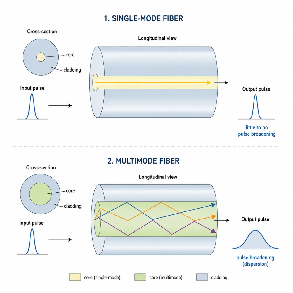
Single-mode fiber guides one main mode with little pulse broadening, while multimode fiber supports several paths that can arrive at different times and cause dispersion.
This educational diagram introduces fiber modes and dispersion by comparing single-mode and multimode optical fibers. In the single-mode fiber, light travels mainly in one guided mode, so the output pulse remains narrow with little broadening. In the multimode fiber, light travels along several guided paths or modes, and these modes can arrive at different times. The output pulse becomes wider, illustrating modal dispersion. The picture helps students understand why fiber design affects signal clarity, communication speed, and transmission distance.
Learning Pathway Within the Fiber Optics Module
Fiber modes and dispersion form the second step in the Fiber Optics cluster. Once students understand how total internal reflection keeps light inside the fiber, the next question is how that light travels as a guided signal. Use the roadmap below to navigate across the cluster levels:
This page explains how optical fibers can act as sensitive measuring devices for strain, temperature, pressure, chemical change, and structural monitoring.
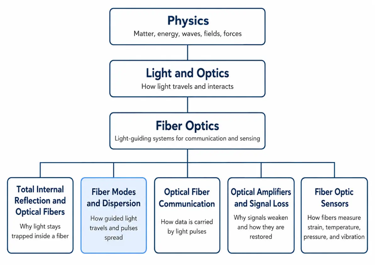
This tree chart shows where Fiber Modes and Dispersion sits within the Fiber Optics cluster, linking the basic guiding principle of total internal reflection to later topics in communication, signal loss, and sensing.
This simple educational tree chart presents the learning pathway for the Fiber Optics cluster on Prep4Uni.online. It begins with Physics, narrows to Light and Optics, then to Fiber Optics, and finally branches into five connected subpages: Total Internal Reflection and Optical Fibers, Fiber Modes and Dispersion, Optical Fiber Communication, Optical Amplifiers and Signal Loss, and Fiber Optic Sensors. The Fiber Modes and Dispersion branch is highlighted to show that it is the second step in the cluster, where students move from the basic idea of guiding light to understanding how guided signals travel, spread, and affect the performance of real fiber-optic systems.
What Fiber Modes and Dispersion REALLY Mean
Fiber modes and dispersion are about the difference between guiding light and preserving a clean signal. Total internal reflection can keep light inside the fiber, but it does not automatically guarantee that every part of the signal arrives at the same time.
Imagine sending a short flash of light into a fiber. If all parts of the flash travel together and arrive together, the signal remains sharp. But if some parts travel a longer path, or some wavelengths travel slightly faster than others, the flash spreads out. A sharp pulse becomes a wider pulse. This matters because fiber-optic communication often uses pulses to represent digital information. If one pulse spreads into the next, the receiver may struggle to decide where one bit ends and the next begins. Dispersion therefore limits how fast data can be sent and how far it can travel without correction.
The key idea is that an optical fiber is not merely a transparent pipe. It is a waveguide. Its size, refractive-index profile, wavelength, material properties, and launch conditions determine which modes can travel and how much dispersion occurs.
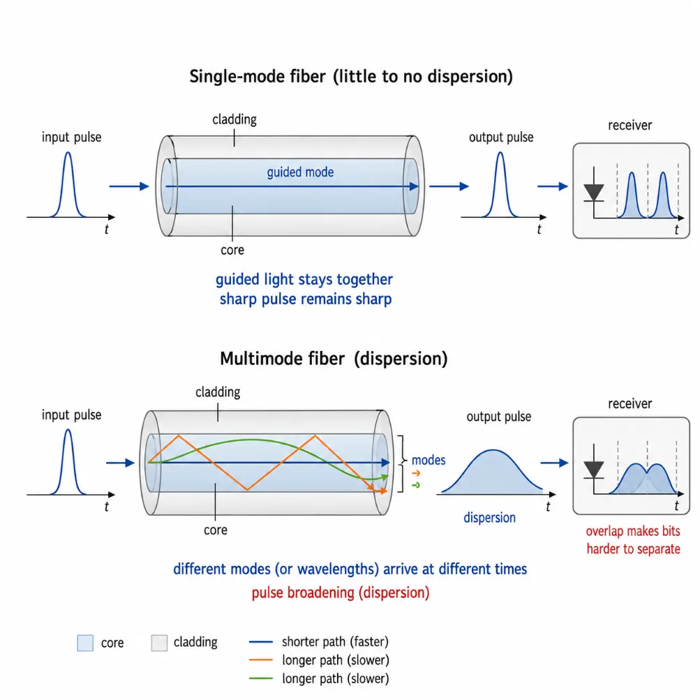
This diagram shows that guiding light inside a fiber is not the same as preserving a clean signal: single-mode fiber keeps pulses sharper, while multimode fiber can cause pulse broadening through dispersion.
This educational diagram explains what fiber modes and dispersion really mean by comparing single-mode and multimode optical fibers. In the upper part, a single-mode fiber guides light in one main mode, so a narrow input pulse remains sharp at the output. In the lower part, a multimode fiber supports several guided paths or modes, and these arrive at different times, causing the output pulse to broaden. The final receiver sketches show that when pulses spread too much, they can overlap and become harder to separate as digital bits. The image helps students see the difference between simply guiding light and preserving signal clarity in fiber-optic communication.
Theoretical Framework: Electromagnetic Waveguide Equations, V-Number Parameters, and Group Velocity Mechanics
To analyze signal distortions with complete undergraduate physical rigor, students must look past simple ray paths and evaluate the electromagnetic field boundaries that dictate wave guide propagation.
The Optical Fiber Waveguide Condition and V-Number
An optical fiber functions structurally as a dielectric cylinder waveguide. Solving Maxwell’s equations inside a step-index fiber requires matching electric and magnetic field equations across the boundaries between the core and cladding. This analysis shows that light fields form distinct transverse electromagnetic distribution layers rather than basic bouncing rays. The total number of guided modes supported by a given fiber architecture depends directly on a dimensionless parameter known as the normalized frequency, or V-number:
Where a is the physical radius of the fiber core, λ0 is the free-space wavelength of the injected light, and NA is the numerical aperture. When the fiber core is engineered to be small enough such that V is less than 2.405, all higher-order spatial patterns reach mode cut-off and escape into the cladding layers. This condition defines a single-mode fiber, leaving only the fundamental core mode (LP01) to propagate. For multi-mode fiber structures where V is significantly larger than2.405, the approximate number of guided spatial paths M can be estimated using the relationship:
$$M \approx \frac{V^2}{2}$$
Group Velocity and Dispersion Constants
While the spatial layout of light is governed by the V-number parameter, the temporal distortion of signals relies on group velocity mechanics. Information packet modulations travel through a medium at the group velocity vg, which is determined by the derivative of the wave propagation constant β with respect to angular frequency ω:
$$\frac{1}{v_g} = \frac{d\beta}{d\omega}$$
Chromatic dispersion occurs because the group velocity varies across different wavelengths. This variation is quantified by the dispersion parameter D, measured in units of ps/(nm·km):
Where n is the refractive index and c is the speed of light in a vacuum. If a fiber link exhibits a positive dispersion parameter D, longer red wavelengths travel more slowly than shorter blue wavelengths, causing a narrow input pulse to broaden over distance.
Ray View versus Wave View of Modes
Ray View: The ray view is useful for building first intuition. In this picture, light travels inside the core and reflects at the core-cladding boundary. Rays that enter at different angles follow different paths. A shallow ray may travel almost straight, while a steeper ray may bounce many times. The ray view helps explain why some rays take longer to reach the end of the fiber. A longer zigzag path generally means a longer travel time. This leads naturally to the idea of modal dispersion.
Wave View: The wave view is more complete. Light is an electromagnetic wave, so only certain field patterns can remain stable inside the fiber. These patterns are the guided modes. In single-mode fibers, the core is small enough that only the fundamental mode is supported at the operating wavelength. The wave view becomes essential for understanding single-mode operation, mode cut-off, chromatic dispersion, polarization effects, and high-speed optical communication.
Refractive Index Profiles and Fiber Architectures
Optical fibers are classified by their physical dimensions and index layouts to balance light capture efficiency against signal distortion constraints:
Step-Index Multimode Fiber: The refractive index changes abruptly at the core-cladding boundary. Because the core has a uniform index profile, rays bouncing at steeper angles travel longer distances than axial rays, leading to severe modal dispersion that restricts transmission speeds.
Graded-Index Multimode Fiber: Features a parabolic refractive index profile that decreases smoothly from the center out toward the cladding. Light rays curve gently instead of zigzagging. Rays traveling farther from the axis pass through lower-index regions where the speed of light is higher, allowing different modes to arrive closer together in time and minimizing modal dispersion.
Single-Mode Fiber (SMF): Constructed with a very narrow core diameter (typically 8 to 10 μm). It confines light to a single spatial path, effectively eliminating modal dispersion and making it the ideal choice for long-distance telecommunications networks.
Classifying the Mechanisms of Optical Dispersion
Dispersion characterizes pulse broadening in time, which should not be confused with attenuation (power loss). The main types of dispersion include:
Dispersion Class
Primary Physical Cause
Impact on Fiber Links
Modal Dispersion
Different spatial modes travel along paths of varying lengths inside the core.
Limits the usable bandwidth of step-index multimode fibers over short distances.
Material Dispersion
The refractive index of silica glass varies across different wavelengths.
Causes components of a pulse to travel at different speeds based on wavelength.
Waveguide Dispersion
The spatial distribution of the light field between the core and cladding changes with wavelength.
Allows engineers to offset material dispersion by tailoring the physical shape of the core.
Polarization Mode Dispersion (PMD)
Asymmetries, stresses, or slight non-circularities cause different polarization states to travel at varying speeds.
Creates a subtle, unpredictable background distortion that limits ultra-high-speed long-haul networks.
When pulses spread too much over distance, they overlap with adjacent signals. This effect is known as inter-symbol interference (ISI), which prevents the receiver from accurately separating digital bits.
Wavelength Selection and Engineering Controls
Optical communication hardware operates within distinct near-infrared transmission windows to balance attenuation limits with low dispersion parameters. The *850 nm window is commonly used for short-distance multimode networks. The 1310 nm window aligns with the zero-dispersion wavelength of standard single-mode fibers, minimizing pulse broadening. The 1550 nm window is preferred for long-haul networks because it offers the lowest attenuation in silica glass and is compatible with erbium-doped fiber amplifiers.
To keep dispersion parameters within safe operating limits, engineers use five main strategies:
Use Single-Mode Fiber: Eliminates modal dispersion pathways completely by restricting propagation to the fundamental mode.
Use Graded-Index Core Materials: Parabolic index adjustments force outer rays to travel faster, keeping modal arrival times synchronized.
Deploy Narrow-Linewidth Laser Sources: Restricting the spectral width of the source limits chromatic pulse spreading.
Utilize Dispersion-Compensating Fiber Modules: Adding segments of fiber with a negative dispersion parameter compensates for accumulated pulse broadening.
Align Operations with Zero-Dispersion Windows: Tuning the emission lasers to operate near the target fiber’s zero-dispersion wavelength suppresses chromatic distortions.
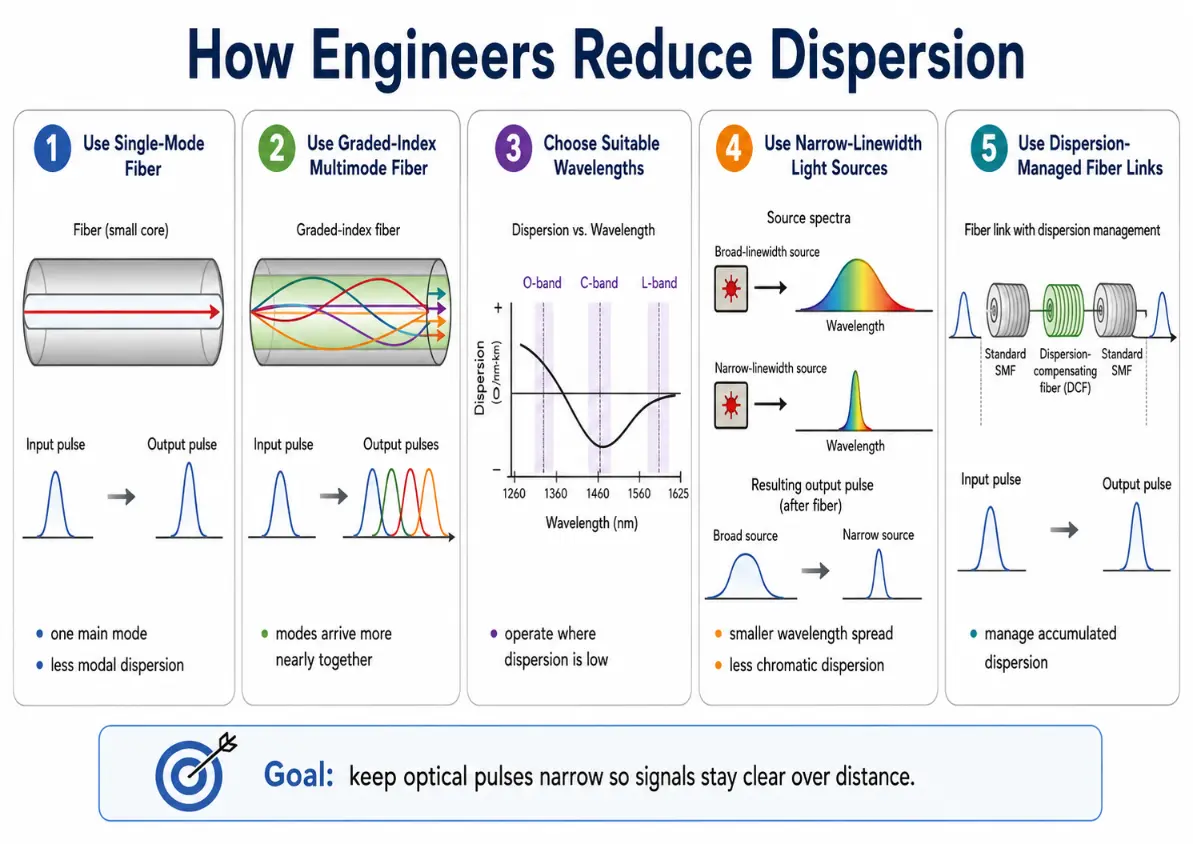
Advanced optimization configurations minimize temporal pulse spreading across high-speed link architectures.
This infographic explains five important strategies engineers use to reduce dispersion in fiber-optic systems. It shows that single-mode fiber helps reduce modal dispersion by guiding only one main mode, while graded-index multimode fiber helps different modes arrive more nearly together. It also highlights the importance of choosing wavelength regions where dispersion is low, using narrow-linewidth light sources to reduce chromatic spreading, and applying dispersion-managed fiber links to control accumulated pulse broadening over long distances. Together, these methods help preserve signal quality and keep optical communication systems fast, clear, and reliable.
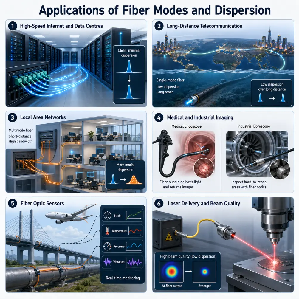
Applications of Mode and Dispersion Mechanics
Understanding field patterns and pulse spreads governs the deployment of modern light-wave networks:
High-Speed Internet and Data Centres
Short-reach interconnect networks use graded-index multimode links to support fast transceivers while keeping coupling costs manageable.
Long-Distance Telecommunication
Undersea cables and transcontinental lines use single-mode fiber links to prevent inter-symbol interference across thousands of kilometers.
Industrial Automation Networks
Factories employ heavy multimode lines to guide data signals securely through high electrical noise environments without alignment risks.
Laser Material Processing
High-power manufacturing lasers utilize specific fiber modes to control the shape and quality of the output beam for clean cutting and welding.
Controlling mode structures and signal spreads determines performance across communication, diagnostics, and high-power laser systems.
This infographic presents six important applications of fiber modes and dispersion. It shows how these ideas affect high-speed internet and data centres, where pulse spreading must be controlled to keep signals clear, and long-distance telecommunication, where single-mode fiber helps maintain low dispersion over great distances. It also highlights local area networks, where multimode fibers are often suitable for shorter links, medical and industrial imaging systems that depend on stable guided light, fiber optic sensors that respond to changes in strain, temperature, pressure, and vibration, and laser delivery systems where the supported fiber modes influence output beam quality. Together, these examples show that fiber modes and dispersion are not just theoretical concepts, but practical factors that shape the performance of real optical technologies.
Common Conceptual Misunderstandings
The Power Attenuation Confusion
Misconception: Dispersion directly weakens the pulse power, making the signal fade out into darkness. Reality: Attenuation reduces signal power. Dispersion distorts the signal by spreading the pulse out in time, meaning the total energy can remain high even if the data becomes unreadable.
The Single-Mode Perfection Illusion
Misconception: Single-mode fibers eliminate all forms of optical dispersion completely. Reality: Single-mode fibers eliminate modal dispersion pathways, but chromatic dispersion and polarization mode dispersion can still cause pulse broadening over long distances.
Interactive Quick Checks
Quick Check: Fiber Modes
1. What is a fiber mode?
A fiber mode is an allowed guided pattern of light propagation inside an optical fiber. In a ray picture, modes can be imagined as different guided paths. In a wave picture, they are stable electromagnetic field patterns supported by the fiber.
2. Why does a multimode fiber usually have more modal dispersion than a single-mode fiber?
A multimode fiber supports many guided modes. These modes can travel different effective distances and arrive at different times, spreading the pulse. A single-mode fiber supports only one main mode, so modal dispersion is greatly reduced.
3. Why is the ray picture useful but incomplete?
The ray picture helps students visualise different paths and travel times. However, real guided light is an electromagnetic wave, and modes are field patterns. A wave view is needed for single-mode fibres, cut-off wavelength, mode field diameter, and advanced dispersion effects.
Quick Check: Dispersion Mechanisms
1. What does dispersion mean in an optical fiber?
Dispersion means that an optical pulse spreads out in time as it travels through the fiber. A narrow input pulse can become a wider output pulse.
2. What is the cause of chromatic dispersion?
Chromatic dispersion occurs because different wavelengths within a light pulse travel at slightly different speeds. It is driven by material dispersion and waveguide dispersion.
3. Why can dispersion cause errors in digital communication?
If pulses spread too much, neighbouring pulses can overlap. The receiver may then have difficulty deciding whether a signal represents a binary 1 or 0, causing data errors.
Numerical Practice: Working Examples
Numerical Problems and Solutions
Worked Example 1: Two light rays travel through a 100 m fiber. One ray follows a nearly straight path of 100 m. Another follows a longer zigzag path of 102 m. If the speed of light in the fiber is approximately 2.0 × 10⁸ m/s, estimate the arrival time difference.
Answer: The ray traveling the longer path arrives approximately 10 ns later.
Worked Example 2: A digital optical system sends pulses every 20 ns. After travelling through a fiber, each pulse broadens to about 8 ns. Is this likely to be acceptable in principle, assuming the pulses remain well separated?
Compare the pulse width with the total slot duration:
The pulse interval is 20 ns, and the broadened pulse width is 8 ns. Because 8 ns is significantly smaller than the 20 ns spacing, the pulses will remain separated without overlapping.
Answer: In principle, this configuration is acceptable because the broadened pulses remain separated. Real-world applications would also need to account for noise margins and receiver limits.
Worked Example 3: If a simple optical link sends one pulse every 10 ns, estimate the corresponding pulse rate.
The transmission rate is the reciprocal of the pulse spacing interval:
Fiber modes and dispersion explain how guided light travels inside optical fibers and why optical pulses may spread as they move. A mode is an allowed guided pattern of light propagation. Multimode fibers support many modes, while single-mode fibers support one main mode at the operating wavelength. Dispersion is pulse spreading. Modal dispersion occurs when different modes arrive at different times. Chromatic dispersion occurs when different wavelengths travel at different speeds. Polarization mode dispersion occurs when different polarization components travel at slightly different speeds. Single-mode fiber is important for long-distance high-bandwidth communication because it greatly reduces modal dispersion. Multimode fiber remains useful for shorter links because it is easier to couple light into and can be cost-effective. Graded-index multimode fiber improves performance by reducing differences in modal arrival time.
Reflection Question
If total internal reflection explains how light stays inside a fiber, what do modes and dispersion teach us about the difference between simply guiding light and preserving useful information?