
Modern robots are not single monolithic programs executing on an isolated processor. Instead, they operate as complex distributed computational networks composed of perception pipelines, state estimation algorithms, motion planners, feedback controllers, hardware drivers, and network communication interfaces. Each of these submodules executes a specialized computational task while continuously exchanging real-time telemetry and control commands with other system nodes.
The Robot Operating System (ROS) provides the foundational software infrastructure that connects these decoupled functional modules. ROS is a distributed robotics middleware framework that orchestrates communication across isolated processes while providing standardized hardware abstraction layers, dynamic simulation interfaces, package management, and system-level diagnostics.
Despite its name, ROS is not a traditional bare-metal operating system like Linux or Windows; it does not directly manage CPU scheduling or physical memory allocation. Instead, it executes within the user space of a host operating system to supply a structured, modular middleware environment in which heterogeneous software processes can communicate, synchronize, and scale across multi-core processors, embedded microcontrollers, and distributed computing clusters.
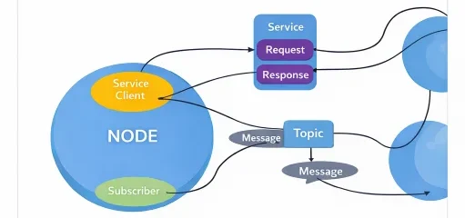
This architecture depicts the decentralized communication topology governing modern robotic software. Individual functional processes (nodes)—such as sensor drivers, state estimators, and motor trajectory controllers—execute in isolated process memory spaces. Nodes interact through standardized message channels: many-to-many asynchronous streaming via topics, point-to-point synchronous transactions via services, and preemptible goal execution pipelines via actions. This modular topology isolates software failures, enables polyglot implementation (C++ and Python), and facilitates seamless transition from simulated environments to physical robotic platforms.
Interactive Quick Review: Fundamentals of ROS & Node Architecture
Test your understanding of robotics middleware and node isolation before exploring publish–subscribe channels:
1. Why is the Robot Operating System (ROS) classified as middleware rather than a traditional operating system?
Answer: Because ROS does not manage low-level hardware memory, interrupt lines, or kernel CPU thread scheduling directly. Instead, it operates on top of an existing host operating system (typically Linux) to provide inter-process communication (IPC), standardized message serialization, hardware driver abstraction, and distributed package management.
2. What architectural advantage is gained by isolating software functions into independent nodes communicating via message passing?
Answer: Process isolation decouples execution memory spaces. An unhandled exception or memory leak in a non-critical module (such as a camera perception filter) will crash only that specific node without destabilizing safety-critical low-level motor controllers. It also enables developers to implement individual modules in different programming languages (e.g., C++ for time-critical control, Python for deep learning).
Glossary of Key Terminology
Essential architectural, algorithmic, and networking definitions governing modern robotics middleware and real-time execution graphs:
std::unique_ptr) directly between subscriber callbacks, completely bypassing network socket serialization and memory duplication.Node-Based Computation and Inter-Process Communication
ROS structures computation into independent modular software entities termed nodes. A physical autonomous machine distributes tasks across an interconnected computation graph where each node \(N_i\) maintains its own internal state \(\mathbf{x}_i(t)\) and memory address space.
Communication between nodes occurs strictly through message passing over three standardized interfaces:
- Topics: Unidirectional, asynchronous, many-to-many publish-subscribe communication channels engineered for continuous streaming data (e.g., high-frequency IMU telemetry, wheel encoder odometry, LiDAR point clouds).
- Services: Synchronous, bidirectional, one-to-one request-response transactions engineered for discrete operational state queries or momentary parameter modifications (e.g., sensor recalibration triggers, kinematic frame queries).
- Actions: Asynchronous, bidirectional, goal-feedback-result client-server interfaces designed for long-running, preemptible tasks requiring continuous execution progress tracking and abort capabilities (e.g., mobile navigation path traversal, manipulator trajectory execution).
Publish–Subscribe Dynamic Formulation
Consider an autonomous mobile robot where an optical encoder node publishes instantaneous joint angle telemetry \(\theta(t)\) at periodic rate \(f = 1/T_s\). A separate control node subscribes to this topic, compares telemetry against target trajectory \(\theta_d(t)\), and evaluates an error signal \(\mathbf{e}(t) = \theta_d(t) - \theta(t)\). In continuous terms, a proportional-derivative feedback controller computes motor command \(\mathbf{u}(t)\):
$$\mathbf{u}(t) = K_p \mathbf{e}(t) + K_d \frac{d\mathbf{e}(t)}{dt}$$When discretized for digital execution across a ROS topic pipeline operating with network transport delay \(\tau_c\), the effective control input evaluated at discrete step \(k\) incorporates physical message latency:
$$\mathbf{u}[k] = K_p \left(\theta_d[k] - \theta\left(t_k - \tau_c\right)\right) + K_d \left(\frac{\theta_d[k] - \theta_d[k-1]}{T_s} - \frac{\theta\left(t_k - \tau_c\right) - \theta\left(t_{k-1} - \tau_c\right)}{T_s}\right)$$If network latency exceeds the controller sampling period (\(\tau_c \ge T_s\)), the controller acts on stale sensory feedback, introducing phase lag that degrades phase margin and triggers unmodeled oscillations.
Architectural Evolution: ROS 1 vs. ROS 2
The transition from legacy ROS 1 to ROS 2 represents an overhaul of underlying communication, networking protocols, and thread scheduling models, addressing safety and production requirements in commercial robotics.
| Architectural Feature | Legacy ROS 1 Architecture | Modern ROS 2 Architecture |
|---|---|---|
| Discovery & Coordination | Centralized XML-RPC Master (roscore); single point of failure. | Decentralized peer-to-peer discovery via DDS multicast; zero master dependency. |
| Transport Protocol | Custom point-to-point sockets (TCPROS, UDPROS). | Industrial OMG DDS standard (UDP/IP, Shared Memory). |
| Quality of Service (QoS) | Rigid TCP queue behavior; high latency over lossy Wi-Fi. | Configurable DDS profiles (Reliability, Durability, History, Deadlines). |
| Real-Time Compatibility | Non-deterministic; dynamic memory allocations throughout core. | Real-time deterministic APIs; zero-copy intra-process transport. |
| Multi-Robot Networking | Requires complex multi-master bridges or custom network tunnels. | Native multi-agent fleets partitioned via ROS_DOMAIN_ID. |
| Cybersecurity | No built-in authentication or encryption; open ports. | SROS 2: TLS/DTLS encryption, X.509 PKI authentication, XML permissions. |
Quality of Service (QoS) Parameterization
ROS 2 exposes deep configuration of communication characteristics through DDS Quality of Service (QoS) policies. Matching publisher and subscriber QoS settings is required for connection compatibility (compatibility rule: Subscriber Requirements \(\le\) Publisher Offerings):
- Reliability:
- Best Effort: Dispatches packets without acknowledgment or retransmission. Minimizes transport latency at the cost of potential packet loss; optimized for high-bandwidth sensor streams (LiDAR, RGB video).
- Reliable: Enforces transport-level ACK/NACK verification with automatic packet retransmission. Guarantees complete data delivery at the expense of variable network latency; mandatory for discrete safety events and trajectory waypoints.
- Durability:
- Volatile: Does not store historical messages; subscribers receive samples published strictly after establishing a connection.
- Transient Local: The publisher node retains the last \(N\) samples in memory, immediately transmitting cached historical data to newly discovered late-joining subscribers (essential for static occupancy grid maps and TF static frame trees).
- History & Depth:
- Keep Last (Depth \(D\)): Maintains a bounded queue storing up to \(D\) incoming messages, discarding the oldest message upon queue overflow to bound RAM consumption.
- Keep All: Preserves every incoming message until external resources are exhausted, risking memory overflow if consumption rates lag production.
Distributed Execution Graphs and Latency Modeling
In autonomous systems, computation occurs along a sequential dataflow pipeline of distributed nodes. Evaluating the end-to-end operational latency from initial photon detection at a camera sensor to physical motor torque output requires calculating cumulative computation times and network transport delays:
$$T_{\text{pipeline}} = \sum_{i=1}^{n} C_i + \sum_{i=1}^{n-1} D_i$$where \(C_i\) represents the worst-case execution time (WCET) of processing stage \(i\), and \(D_i\) is the inter-node communication latency between consecutive nodes.
For real-time control feasibility, the total pipeline latency must strictly satisfy the maximum allowable physical deadline:
$$T_{\text{pipeline}} \le T_{\text{deadline}}$$If \(T_{\text{pipeline}} > T_{\text{deadline}}\), the control command arrives after the valid control period, requiring either algorithmic simplification, intra-process zero-copy optimization, or thread priority escalation via real-time kernel patches.
Engineering Challenges & Technical Solutions
Deploying distributed robotics middleware across physical hardware, embedded platforms, and wireless networks presents several practical computational and network engineering challenges:
The Challenge: Standard DDS discovery relies on continuous UDP multicast packets. In warehouse environments containing dozens of mobile robots on a single Wi-Fi access point, discovery packets scale quadratically (\(\mathcal{O}(N^2)\)), causing discovery storms, packet loss, and Wi-Fi link saturation.
- Domain ID Partitioning: Assigning unique
ROS_DOMAIN_IDvalues (0–232) to isolate physical robot teams onto independent multicast socket ports. - DDS Discovery Server Architecture: Disabling broadcast discovery in favor of a centralized or redundant Discovery Server (e.g., Fast DDS Discovery Server), routing participant registrations via point-to-point unicast TCP/UDP connections.
The Challenge: High-bandwidth sensors (e.g., 4K color cameras, 128-beam LiDAR point clouds) generate dozens of megabytes per second. Serializing, copying, and deserializing this data across standard Linux inter-process boundaries consumes significant CPU resources and memory bandwidth.
- Component Container Composition: Loading multiple node plugins into a single OS process container (
rclcpp_components) to execute within a shared memory space. - Zero-Copy Shared Memory Transport: Utilizing loan-message APIs and Eclipse iceoryx middleware integration, passing direct memory pointers between publishers and subscribers without copying bytes.
The Challenge: A single-threaded executor processes callbacks sequentially in a FIFO queue. If an intensive image processing callback runs for 50 ms, high-priority 1 kHz motor control timer callbacks queued behind it are delayed, causing missed control deadlines.
- Mutually Exclusive Callback Groups: Partitioning sensor parsing and motor control callbacks into isolated callback groups managed by a
MultiThreadedExecutoracross dedicated thread pools. - Real-Time Callback Schedulers: Pinning critical actuator threads to dedicated CPU cores with real-time FIFO scheduling priorities (
SCHED_FIFO) on PREEMPT_RT Linux kernels, as detailed in Real-Time Embedded Systems in Robotics.
The Challenge: Standard DDS networks communicate in plain text. Malicious actors on the same subnetwork can sniff sensor feeds, spoof unauthorized velocity commands (/cmd_vel), or issue node-shutdown commands.
- SROS 2 Public Key Infrastructure: Enforcing X.509 certificate generation, ensuring only authenticated nodes with valid cryptographic keys can join the DDS computational domain.
- DDS-Security Access Control: Deploying signed XML governance and permissions files that specify which specific topics and services each node can access, while encrypting payloads via AES-GCM (128/256-bit).
Interactive Quick Review: DDS, QoS & SROS 2 Security
Reinforce key concepts regarding peer-to-peer discovery, QoS policy selection, and network security before reviewing the FAQ:
1. How does ROS 2 eliminate the single point of failure inherent in ROS 1's centralized master?
Answer: ROS 2 utilizes the Data Distribution Service (DDS) middleware, which implements decentralized peer-to-peer node discovery via UDP multicasting, eliminating the need for a central lookup master.
2. When should a developer select a "Best Effort" QoS policy over a "Reliable" QoS policy?
Answer: Best Effort is ideal for high-frequency sensor streams (such as 30 Hz camera feeds or LiDAR point clouds) where low latency is critical and dropping an occasional stale frame is acceptable.
External References and Further Reading
To explore official documentation, development tutorials, and middleware standard specifications, consult the following authoritative sources:
- ROS 2 Documentation & Tutorials – The official developer portal covering ROS 2 architecture, rclcpp/rclpy client libraries, and launch configurations.
- Object Management Group (OMG) DDS Specification – Official technical standard for the Data Distribution Service protocol underpinning ROS 2 communications.
- SROS 2 Security Repository – Open-source security documentation for PKI key management, access control, and TLS/DDS-Security integration in ROS 2.
Frequently Asked Questions about ROS and ROS 2
What is the difference between ROS Topics, Services, and Actions?
Topics use an asynchronous many-to-many publish-subscribe pattern for continuous data feeds (e.g., sensor streams). Services use a synchronous one-to-one request-response pattern for quick execution tasks (e.g., querying a sensor state). Actions use an asynchronous goal-feedback-result pattern for long-running tasks that provide ongoing status updates and can be canceled (e.g., navigating to a distant room).
Why was ROS 2 redesigned from scratch rather than simply updating ROS 1?
ROS 1 was designed for single-robot research setups with reliable wired networks. Redesigning ROS 2 on DDS allowed native support for multi-robot fleets, unreliable wireless networks, real-time microcontrollers (micro-ROS), commercial security standards (SROS 2), and production-grade safety certification.
What is micro-ROS, and how does it extend ROS 2 to microcontrollers?
micro-ROS is an extension framework that enables resource-constrained microcontrollers (like ARM Cortex-M or ESP32) to act as native ROS 2 nodes. It uses the Micro-XRCE-DDS protocol to bridge low-level embedded hardware directly to ROS 2 topic graphs.
How do client libraries (rclcpp and rclpy) interact with the ROS 2 architecture?
rclcpp (C++) and rclpy (Python) are language-specific user APIs that sit on top of the common C-based ROS Client Library (rcl). The rcl library interfaces with the ROS Middleware layer (rmw), which abstracts the underlying DDS implementation (e.g., eProsima Fast DDS or Cyclone DDS).
What is a ROS 2 Launch file, and why is Python used for launch scripts?
A launch file automates starting, configuring, and connecting complex multi-node robotic systems. ROS 2 uses Python for launch files because it permits programmatic control, such as conditional node execution based on hardware parameters or network states.
How does the TF2 transform library manage spatial relationships in ROS?
TF2 is a coordinate frame tracking system that maintains a dynamic tree of 3-D spatial transformations over time. It allows nodes to query historical spatial relationships between coordinate frames (e.g., mapping a point detected in a camera frame to the robot's base frame).
What security tools are provided by SROS 2?
SROS 2 provides command-line utilities to generate Public Key Infrastructure (PKI) certificates, encrypt network traffic using TLS/DTLS, and enforce XML permission profiles that dictate which topics a specific node is allowed to publish or subscribe to.
What university backgrounds best prepare students for ROS/ROS 2 software development?
Students should develop strong foundations in computer science, software engineering, Linux system programming, C++/Python object-oriented programming, concurrent multi-threading, and network protocols alongside basic control theory.
End-of-Page Exercises: Review, Thought-Provoking & Engineering Problems
Section 1: Foundational Review Questions & Answers
1. What three core communication patterns are supported in ROS?
Answer: Topics (asynchronous publish–subscribe), Services (synchronous request–response), and Actions (asynchronous goal–feedback–result).
2. What central component in ROS 1 managed node discovery and registration?
Answer: The ROS Master (roscore), which ran an XML-RPC server mapping node names to IP endpoints.
3. What communication protocol forms the foundation of decentralized networking in ROS 2?
Answer: Data Distribution Service (DDS), an OMG industrial peer-to-peer middleware standard.
4. How is the sampling period T calculated from a topic update frequency f?
Answer: \(T = 1 / f\), representing the temporal duration between consecutive message publications.
5. What formula calculates the total end-to-end latency across a sequential node pipeline?
Answer: \(T_{\text{total}} = \sum C_i + \sum D_i\), summing execution compute times \(C_i\) and inter-node transport delays \(D_i\).
6. Name two Quality of Service (QoS) durability policies available in ROS 2.
Answer: Transient Local (retains historical messages for late-joining subscribers) and Volatile (discards messages immediately, retaining no history).
7. What condition must pipeline latency satisfy to ensure real-time feasibility?
Answer: \(T_{\text{total}} \le T_{\text{deadline}}\), ensuring control output generation occurs before the control period expires.
8. What security extension framework provides encryption and authentication for ROS 2?
Answer: SROS 2 (Secure ROS 2), integrating DDS-Security with X.509 PKI certificates and TLS/DTLS encryption.
9. What library in ROS manages coordinate frame transformations over time?
Answer: The TF2 transform library.
10. Name the two primary programming language client libraries in ROS 2.
Answer: rclcpp (C++) and rclpy (Python).
Section 2: Analytical & Thought-Provoking Questions
1. How does the choice between process-based node execution and intra-process zero-copy communication impact CPU overhead in ROS 2?
Answer: Standard process-based nodes pass messages via network sockets or IPC buffers, requiring data serialization, memory copying, and context switching. Component containers utilizing intra-process zero-copy pass pointer references directly through shared memory, eliminating serialization overhead and reducing latency to sub-microsecond levels for heavy data payloads like 4K video streams.
2. Why can network packet loss cause catastrophic control instability when using "Best Effort" QoS on a wireless robot fleet?
Answer: Best Effort QoS drops lost packets without retransmission. If a wireless link experiences severe interference, consecutive control or state messages are lost. The subscriber controller continues operating on the last received command or freezes, introducing uncompensated phase lag and physical drift that can lead to physical collisions before connection resumes.
3. What security vulnerabilities exist in ROS 1 networks operating on unencrypted TCP/UDP ports?
Answer: ROS 1 has no built-in authentication or encryption. Any device on the same local network can query the ROS Master, eavesdrop on sensitive sensor topics, spoof false velocity commands (/cmd_vel), or kill active nodes remotely, posing severe physical safety and data privacy risks in industrial settings.
4. How do executor models (Single-Threaded vs. Multi-Threaded) in ROS 2 affect callback execution determinism?
Answer: A Single-Threaded Executor processes topic callbacks sequentially in a single FIFO queue; if a vision callback blocks for 50 ms, it delays high-priority control callbacks queued behind it. Multi-Threaded Executors distribute callbacks across worker thread pools, enabling parallel execution on multi-core CPUs, though careful mutex locking is required to prevent race conditions.
5. Why is a Service pattern inappropriate for transmitting continuous 100 Hz IMU orientation data?
Answer: Services enforce synchronous one-to-one blocking request-response cycles. Expecting a subscriber to send 100 explicit requests per second introduces massive network round-trip overhead and halts execution while awaiting replies. Topics use lightweight asynchronous streaming, pushing data continuously without blocking the sender.
6. How does domain separation (ROS_DOMAIN_ID) prevent cross-talk between multiple robots on a shared network?
Answer: ROS_DOMAIN_ID maps directly to the underlying DDS Domain ID parameter (0–232). DDS discovery traffic uses multicast ports mathematically calculated from the Domain ID. Assigning different IDs ensures that discovery packets remain isolated to specific domain ports, allowing independent robots to share physical Wi-Fi channels without cross-subscribing.
7. Why do real-time control applications require memory locking (mlockall()) when running ROS 2 nodes on PREEMPT_RT Linux?
Answer: Linux uses virtual memory paging; if a ROS 2 thread accesses memory pages swapped to disk, it triggers a page fault that stalls process execution for milliseconds while reading from disk. mlockall() locks the process address space directly into physical RAM, eliminating page fault delays to preserve microsecond execution determinism.
8. What challenges arise when parameterizing DDS QoS profiles for heterogeneous networks (e.g., combining wired Ethernet with high-latency satellite links)?
Answer: A rigid Reliable QoS configuration over satellite links causes packet queue congestion, buffer overflows, and blocking delays due to long round-trip ACK/NACK acknowledgments. Developers must tune keep-last depth limits, max blocking times, and heartbeats to decouple real-time local loops from distant telemetry channels.
9. How does ROS 2 parameter dynamic reconfiguration allow real-time tuning of control gains without restarting nodes?
Answer: ROS 2 nodes host internal parameter servers built on standard service interfaces. External tuning utilities (like rqt_reconfigure) send parameter update service requests to the node at runtime. Parameter change callbacks intercept these events and update internal controller gains dynamically without breaking thread loops.
10. Why is non-blocking execution essential within the goal-response phase of an Action server?
Answer: The goal-response phase must accept or reject a new goal instantaneously. If the Action server blocks its main execution thread while performing the goal task, it stops processing feedback updates, ignores cancel requests, and halts communication with the rest of the ROS network.
11. How does the lifecycle node management model (LifecycleNode) improve system safety in industrial automation?
Answer: Lifecycle nodes enforce a managed state machine (Unconfigured, Inactive, Active, Finalized). Nodes only publish commands or process sensor updates when in the Active state. System orchestrators can safely initialize and calibrate hardware drivers in the Inactive state before activating production loops, preventing erratic startup commands.
12. What role does message serialization (e.g., CDR format in DDS) play in heterogeneous CPU architectures (x86 vs. ARM)?
Answer: Different CPU architectures may store multi-byte numbers using different endianness (little-endian vs. big-endian) or data alignment rules. Common Data Representation (CDR) normalizes C++ structs into a standardized, architecture-agnostic binary byte stream, allowing an x86 workstation to communicate seamlessly with an ARM microcontroller.
Section 3: Numerical Engineering Problems & Solutions
A high-resolution optical wheel encoder node publishes joint velocity telemetry on a ROS 2 topic at nominal frequency \(f = 250\text{ Hz}\). Calculate the exact nominal sampling period \(T\) in milliseconds. If network queuing introduces an arrival jitter delay of \(\Delta t = 6.0\text{ ms}\), calculate the effective arrival interval \(T_{\text{effective}}\) and the percentage timing deviation relative to nominal.
1. Calculate nominal sampling period: $$T = \frac{1}{f} = \frac{1}{250\text{ s}^{-1}} = 0.004\text{ s} = 4.0\text{ ms}$$ 2. Calculate effective arrival interval: $$T_{\text{effective}} = T + \Delta t = 4.0\text{ ms} + 6.0\text{ ms} = 10.0\text{ ms}$$ 3. Compute percentage deviation: $$\% \text{ Deviation} = \frac{T_{\text{effective}} - T}{T} \times 100 = \frac{10.0 - 4.0}{4.0} \times 100 = \frac{6.0}{4.0} \times 100 = 150.0\%$$ Final Answer: Nominal period is \(4.0\text{ ms}\); effective arrival interval is \(10.0\text{ ms}\) (a \(150.0\%\) timing deviation).
An autonomous mobile robot processes 3D LiDAR point clouds across a four-stage sequential ROS 2 node computation pipeline:
- Stage 1 (LiDAR Driver Node): computation \(C_1 = 4.5\text{ ms}\), network transport delay \(D_1 = 1.2\text{ ms}\)
- Stage 2 (Voxel Clustering Node): computation \(C_2 = 12.0\text{ ms}\), network transport delay \(D_2 = 1.8\text{ ms}\)
- Stage 3 (Local Path Planner Node): computation \(C_3 = 8.5\text{ ms}\), network transport delay \(D_3 = 1.5\text{ ms}\)
- Stage 4 (Motor Controller Node): computation \(C_4 = 2.5\text{ ms}\), network transport delay \(D_4 = 0.0\text{ ms}\) (direct hardware bus write)
1. Calculate cumulative computation time: $$\sum_{i=1}^{4} C_i = 4.5 + 12.0 + 8.5 + 2.5 = 27.5\text{ ms}$$ 2. Calculate cumulative communication latency: $$\sum_{i=1}^{4} D_i = 1.2 + 1.8 + 1.5 + 0.0 = 4.5\text{ ms}$$ 3. Compute total end-to-end pipeline latency: $$T_{\text{total}} = \sum C_i + \sum D_i = 27.5 + 4.5 = 32.0\text{ ms}$$ 4. Verify real-time constraint: $$32.0\text{ ms} \le 35.0\text{ ms} \quad (\text{Constraint Satisfied})$$ Final Answer: Total latency is \(32.0\text{ ms}\); the pipeline satisfies the deadline with a \(3.0\text{ ms}\) safety margin.
An RGB-D perception node publishes uncompressed \(1920 \times 1080\) resolution image messages over a ROS 2 network topic at a frame rate of \(30\text{ fps}\). Each raw image payload occupies \(S = 6.2\text{ Megabytes (MB)}\). Calculate the raw data throughput in Megabytes per second (MB/s) and convert this throughput to Megabits per second (Mbps). (Given: \(1\text{ Byte} = 8\text{ bits}\)).
1. Compute throughput in Megabytes per second: $$\text{Throughput}_{\text{MB/s}} = S \times f = 6.2\text{ MB/frame} \times 30\text{ frames/s} = 186.0\text{ MB/s}$$ 2. Convert Megabytes to Megabits per second: $$\text{Throughput}_{\text{Mbps}} = 186.0\text{ MB/s} \times 8\text{ bits/Byte} = 1488.0\text{ Mbps} = 1.488\text{ Gbps}$$ Final Answer: Topic throughput is \(186.0\text{ MB/s}\) (or \(1488.0\text{ Mbps}\)), demonstrating that uncompressed transmission saturates standard 1-Gigabit Ethernet links.
A robotic joint position control node subscribes to an odometry topic publishing current joint angle \(\theta(t) = 0.82\text{ radians}\). The node compares this against reference trajectory setpoint \(\theta_d = 1.20\text{ radians}\). Using a configured proportional gain of \(K = 15.0\text{ N}\cdot\text{m/rad}\), calculate the angular tracking error \(e(t) = \theta_d - \theta(t)\) and the output control torque command \(u(t) = K e(t)\).
1. Calculate instantaneous tracking error: $$e(t) = 1.20\text{ rad} - 0.82\text{ rad} = 0.38\text{ radians}$$ 2. Compute proportional torque command: $$u(t) = K e(t) = 15.0\text{ N}\cdot\text{m/rad} \times 0.38\text{ rad} = 5.70\text{ N}\cdot\text{m}$$ Final Answer: Tracking error is \(0.38\text{ rad}\) and commanded actuator torque is \(u(t) = 5.70\text{ N}\cdot\text{m}\).
A subscriber node sets a "Keep Last" QoS history policy with a queue depth of \(N_{\text{depth}} = 50\text{ samples}\) for an incoming
sensor_msgs/msg/PointCloud2 topic. Each point cloud sample occupies \(M = 450\text{ Kilobytes (KB)}\). Calculate the total memory allocated for the message queue buffer in Kilobytes and Megabytes. (Given: \(1\text{ MB} = 1024\text{ KB}\)).1. Compute total buffer size in Kilobytes: $$\text{RAM}_{\text{KB}} = N_{\text{depth}} \times M = 50 \times 450\text{ KB} = 22500\text{ KB}$$ 2. Convert Kilobytes to Megabytes: $$\text{RAM}_{\text{MB}} = \frac{22500\text{ KB}}{1024\text{ KB/MB}} \approx 21.9726\text{ MB}$$ Final Answer: Reserved QoS queue buffer memory is \(22500\text{ KB}\) (approximately \(21.97\text{ MB}\)).
An aerial drone attitude stabilization loop executes on an embedded ROS 2 node at a control sampling period of \(T_s = 4.0\text{ ms}\) (\(250\text{ Hz}\)). Telemetry messages are transmitted over a wireless link experiencing variable communication latency \(\tau\). If network telemetry benchmarks measure current delay at \(\tau = 2.8\text{ ms}\), verify whether \(\tau < T_s\) is satisfied and compute the remaining latency safety margin.
1. Evaluate latency condition: $$\tau = 2.8\text{ ms} < 4.0\text{ ms} = T_s \quad (\text{Condition Satisfied})$$ 2. Calculate remaining timing headroom: $$\text{Margin} = T_s - \tau = 4.0\text{ ms} - 2.8\text{ ms} = 1.2\text{ ms}$$ Final Answer: Latency constraint is satisfied with a remaining margin of \(1.2\text{ ms}\).
A digital twin simulation environment running in Isaac Sim mirrors a physical manipulator. Telemetry nodes measure physical joint rotational velocity \(x_{\text{real}}(t) = 2.45\text{ rad/s}\) while the synchronized simulation model predicts \(x_{\text{sim}}(t) = 2.50\text{ rad/s}\). Calculate the absolute error \(e_{\text{abs}} = |x_{\text{real}} - x_{\text{sim}}|\) and the relative percentage deviation relative to physical truth.
1. Calculate absolute error: $$e_{\text{abs}} = |2.45 - 2.50| = |-0.05| = 0.05\text{ rad/s}$$ 2. Compute relative percentage deviation: $$\% \text{ Error} = \frac{e_{\text{abs}}}{x_{\text{real}}} \times 100 = \frac{0.05}{2.45} \times 100 \approx 2.0408\%$$ Final Answer: Absolute deviation is \(0.05\text{ rad/s}\), representing a \(2.04\%\) relative simulation error.
A SLAM localization client node invokes a synchronous map query service (
nav_msgs/srv/GetMap). The serialized request transmission takes \(t_{\text{req}} = 1.5\text{ ms}\), server-side map extraction takes \(t_{\text{calc}} = 8.0\text{ ms}\), and response payload transmission takes \(t_{\text{res}} = 2.5\text{ ms}\). Calculate the total blocking round-trip time (\(T_{\text{RTT}}\)) experienced by the calling client thread.1. Apply round-trip accumulation formula: $$T_{\text{RTT}} = t_{\text{req}} + t_{\text{calc}} + t_{\text{res}} = 1.5\text{ ms} + 8.0\text{ ms} + 2.5\text{ ms} = 12.0\text{ ms}$$ Final Answer: Total synchronous blocking round-trip time is \(12.0\text{ ms}\).
A trajectory action server executes a mobile navigation goal lasting \(T_{\text{action}} = 8.0\text{ seconds}\). The action server is parameterized to dispatch incremental progress feedback packets every \(\Delta t_{\text{fb}} = 200\text{ ms}\). Calculate the total count of feedback messages \(N_{\text{feedback}}\) generated throughout the execution window.
1. Convert total duration to milliseconds: $$T_{\text{action}} = 8.0\text{ s} \times 1000\text{ ms/s} = 8000\text{ ms}$$ 2. Calculate total feedback packets: $$N_{\text{feedback}} = \frac{T_{\text{action}}}{\Delta t_{\text{fb}}} = \frac{8000\text{ ms}}{200\text{ ms}} = 40\text{ messages}$$ Final Answer: The action server publishes \(40\text{ feedback messages}\) during trajectory execution.
A high-throughput ROS 2 component container executes on a quad-core processor using a
MultiThreadedExecutor configured with 4 worker threads. Performance profiling under peak operational load indicates Thread 1 utilization is \(80\%\), Thread 2 is \(65\%\), Thread 3 is \(50\%\), and Thread 4 is \(45\%\). Calculate the overall average worker thread CPU utilization across the executor pool.1. Sum individual thread utilization percentages: $$\sum U_i = 80\% + 65\% + 50\% + 45\% = 240\%$$ 2. Divide by the number of thread workers (\(N_{\text{threads}} = 4\)): $$\bar{U} = \frac{\sum U_i}{N_{\text{threads}}} = \frac{240\%}{4} = 60.0\%$$ Final Answer: Average executor worker thread utilization is \(60.0\%\).
Enabling SROS 2 AES-GCM (128-bit) cryptographic payload encryption and authentication adds a fixed cryptographic processing delay of \(t_{\text{crypto}} = 0.8\text{ ms}\) per topic message. If an unencrypted DDS transmission requires \(t_{\text{raw}} = 1.2\text{ ms}\), calculate the total encrypted transmission time \(t_{\text{secure}}\) and determine the percentage latency overhead introduced by security.
1. Calculate total secure transmission latency: $$t_{\text{secure}} = t_{\text{raw}} + t_{\text{crypto}} = 1.2\text{ ms} + 0.8\text{ ms} = 2.0\text{ ms}$$ 2. Compute percentage latency increase: $$\% \text{ Overhead} = \frac{t_{\text{secure}} - t_{\text{raw}}}{t_{\text{raw}}} \times 100 = \frac{0.8}{1.2} \times 100 \approx 66.6667\%$$ Final Answer: Encrypted transmission latency is \(2.0\text{ ms}\), representing a \(66.67\%\) overhead increase.
A TF2 transform buffer maintains a historical transform cache window of \(T_{\text{cache}} = 10.0\text{ seconds}\). A robot joint state publisher broadcasts dynamic link transform updates at a rate of \(100\text{ Hz}\). If each binary transform record occupies \(128\text{ bytes}\) of structured memory, calculate the total memory required to buffer this single coordinate frame pair in bytes and Kilobytes. (Given: \(1\text{ KB} = 1000\text{ bytes}\)).
1. Calculate total transform records buffered over the cache window: $$N_{\text{records}} = T_{\text{cache}} \times f = 10.0\text{ s} \times 100\text{ records/s} = 1000\text{ records}$$ 2. Compute total buffer memory footprint: $$\text{RAM}_{\text{bytes}} = 1000\text{ records} \times 128\text{ bytes/record} = 128000\text{ bytes}$$ 3. Convert to Kilobytes: $$\text{RAM}_{\text{KB}} = \frac{128000\text{ bytes}}{1000\text{ bytes/KB}} = 128.0\text{ KB}$$ Final Answer: The 10-second TF2 transform cache requires \(128000\text{ bytes}\) (or \(128.0\text{ KB}\)) of RAM.
Robot Operating System (ROS and ROS 2) — Summary & Wrap-Up
The Robot Operating System (ROS and ROS 2) forms the universal software infrastructure of modern robotics. By structuring complex computational pipelines into isolated nodes, enabling asynchronous topic streaming, synchronous service calls, long-running actions, and peer-to-peer DDS discovery with configurable Quality of Service (QoS) and SROS 2 encryption, ROS converts independent algorithms into robust, real-time, and scalable autonomous platforms.
Explore Robotics Software and Infrastructure
The Robot Operating System forms the communication backbone of modern robotics, operating within a broader ecosystem of software technologies. Simulation environments, embedded control platforms, distributed middleware architectures, and cloud computing frameworks all interact with ROS-based systems to enable complex robotic applications.
The following pages explore these complementary technologies and how they contribute to the overall robotics software infrastructure:
Robotics Simulation Platforms
Simulation tools allow ROS-based algorithms to be tested within virtual environments before deployment on physical robots, improving development efficiency and safety.
Real-Time Embedded Systems in Robotics
Embedded processors execute control loops and hardware interfaces that interact with ROS nodes responsible for higher-level decision-making and system coordination.
Robotics Middleware and Distributed Systems
Middleware frameworks coordinate communication between multiple computers in distributed robotic architectures, extending ROS-based systems across complex networks.
Robotic Digital Twin Systems and Simulation
Digital twin models connect ROS-driven robots with synchronized virtual environments, enabling predictive analysis and safe testing of new algorithms.
Cloud Robotics and Edge Intelligence
Cloud robotics platforms extend ROS architectures by enabling robots to access remote computation, shared datasets, and distributed learning systems.