
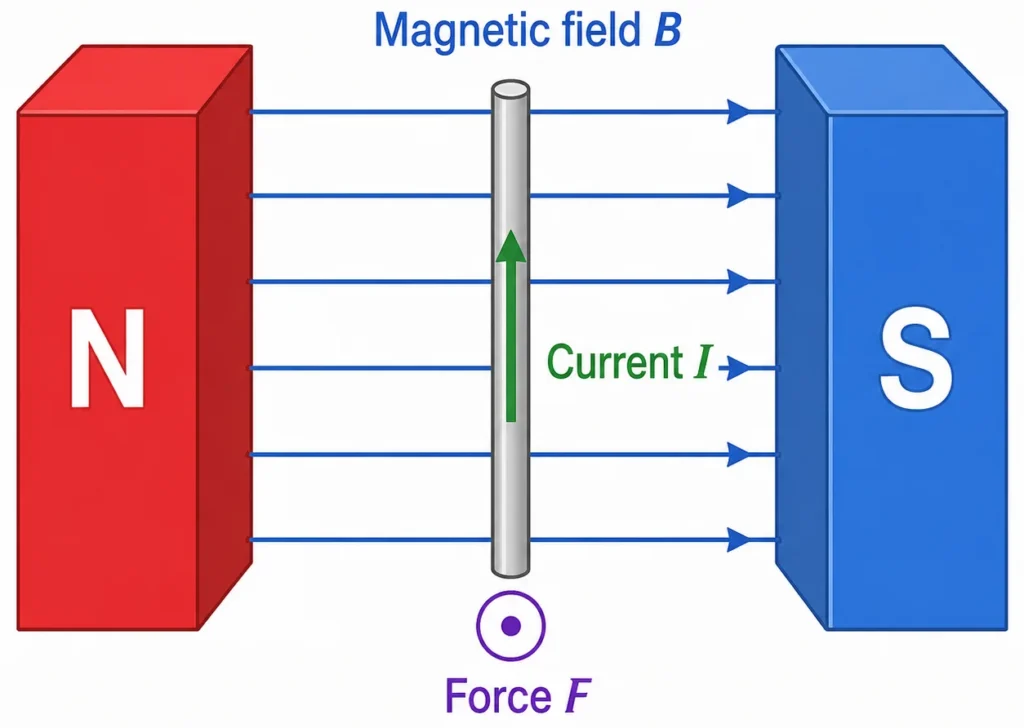
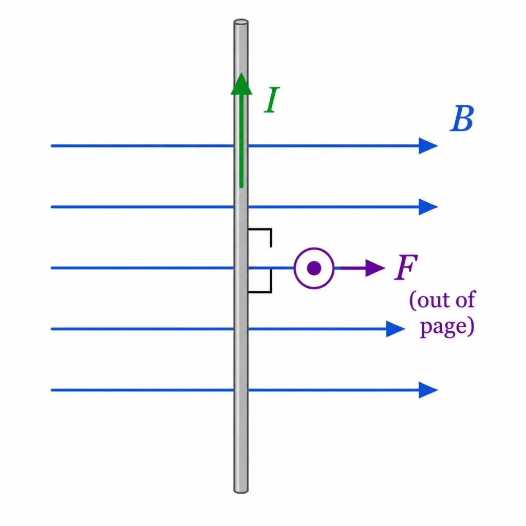
This illustration shows a straight wire carrying current between the north and south poles of a magnet. The magnetic field runs across the gap between the poles, while the current flows along the wire. Because the current and magnetic field are at right angles, the wire experiences a magnetic force perpendicular to both directions. The picture helps students see the three-direction relationship between magnetic field, current, and force, which is the basic physical effect behind motors, speakers, and other electromagnetic devices.
Magnetic Fields Learning Pathway
Electricity and Magnetism Context
Provides the global parent context for understanding charge distributions, vector fields, electric circuits, induction, and Maxwellian wave mechanics.Magnetic Fields Parent Hub
Introduces how magnetic fields modify space to exert forces, guide moving charges, and support solid-state measurement technologies.Magnetic Force on Moving Charges
Quantifies the velocity-dependent mechanical force vectors experienced by point charges navigating external magnetic flux distributions.Magnetic Force on Current Wires
Extends magnetic force from moving charges to a wire carrying current, explaining how magnetic fields can push conductors and produce motion.Motion of Charges in Magnetic Fields
Models the orbital and helical trajectory mechanics that occur when a perpendicular magnetic deflection acts as a constant centripetal constraint.Hall Effect and Magnetic Measurement
Analyzes the cross-boundary charge separation that occurs inside solid-state conductors, converting magnetic field metrics into measurable Hall voltages.The Core Physical Idea
Current, Magnetic Field, and Force Direction
Effect of the Angle Between Wire and Field
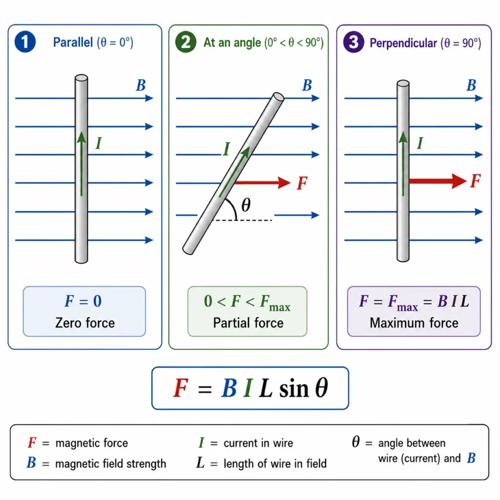
This illustration compares three orientations of a current-carrying wire in a magnetic field. When the wire is parallel to the magnetic field, the magnetic force is zero. When the wire is at an angle, only part of the current direction is perpendicular to the field, so the force is partial. When the wire is perpendicular to the magnetic field, the force is maximum and is given by F = BIL. The picture helps students understand the sin θ term in the equation F = BIL sin θ.
The Motor Effect in Rotating Coils
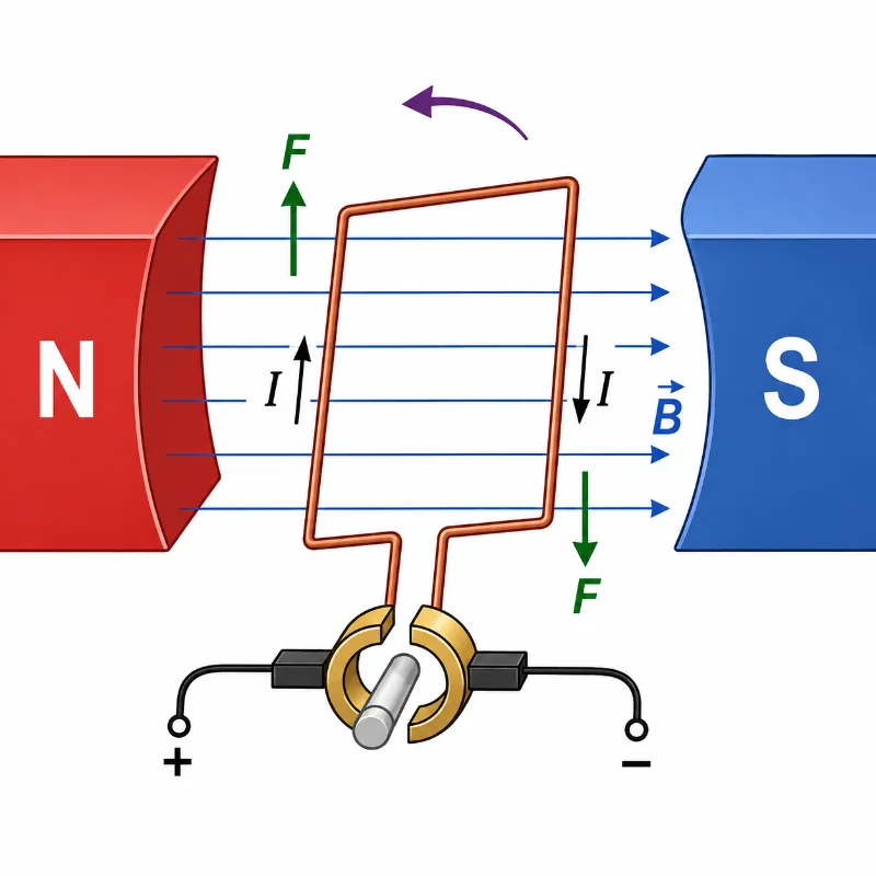
This illustration shows the motor effect in a current-carrying coil placed between magnetic poles. Current flows in opposite directions on the two sides of the coil, so the magnetic field produces forces in opposite directions on those sides. These opposite forces create a turning effect, causing the coil to rotate. The picture helps students connect the magnetic force on a straight current-carrying wire to the basic working principle of electric motors.
Determining the Force Vector Direction
First Finger: Index for Field
Align the index finger straight along the direction of the magnetic field vector, pointing from the North pole face toward the South pole face.
Second Finger: Middle for Current
Align the middle finger perpendicular to the index, pointing along the direction of conventional current (from positive potential toward negative potential).
The Thumb: Mechanical Force
Extend the thumb out at a right angle. The thumb points directly along the vector line of the resulting mechanical force or wire displacement.
The Primary Principle to Remember
A magnetic field can exert mechanical pressure on a conductor only if an active current passes through the wire, and that current contains a vector component running perpendicular to the field lines.
Advanced Mathematical Rigor: Microscopic Origins and Differential Integrals
Technical Case Studies: Applied Magnetostatic Engineering
Acoustic Engineering: Dynamic Voice-Coil Loudspeakers
High-fidelity audio speakers use an alternating current voice coil suspended inside a powerful, radially oriented permanent magnetic field. When the connected amplifier sends alternating audio current signals through the coil, the changing current vector drives a rapidly shifting mechanical force (F = BIL sin θ) along the coil’s axis. This forces the voice coil to move back and forth at the exact frequency of the audio signal, vibrating the attached speaker cone to convert electrical signals into acoustic sound waves.
High-Speed Transportation: Maglev Propulsion Systems
Super-fast Maglev trains replace traditional mechanical wheels and tracks with massive electromagnetic propulsion loops. The train cars carry powerful superconducting magnets that lock into trackside guiding walls containing current-carrying stator coils. Computer-controlled three-phase currents pass through these track loops, generating precise magnetic forces (F = ∫ I dl × B) that pull the train forward while maintaining stable magnetic levitation, allowing the train to cruise at over 500 km/h without mechanical friction.
Evolution of Magnetic Conductor Theory: History and Future Frontiers
Historical Epochs: From Ampère’s Current Loops to Maxwellian Mechanics
Future Technological Horizons: Room-Temperature Superconducting Power Grids
Numerical Problems and Solutions
-
A straight conductor wire section of length 0.40 m carries a current of 3.0 A perpendicular to a uniform 0.50 T magnetic field. Calculate the resulting mechanical force.Solution: Apply the perpendicular conductor force equation:$$F = BIL \Rightarrow F = (0.50\text{ T})(3.0\text{ A})(0.40\text{ m}) = 0.60\text{ N}$$Interpretation: The wire experiences a net mechanical force of exactly 0.60 N, directed perpendicular to both the current path and the magnetic field lines according to vector rules.
-
A straight wire is placed perfectly parallel to an active magnetic field vector. Determine the total mechanical force acting on the conductor if it carries a current of 5.0 A.Solution: Evaluate using the general angle-dependent equation:$$F = BIL\sin\theta \quad (\text{where } \theta = 0^{\circ} \Rightarrow \sin(0^{\circ}) = 0)$$ $$F = BIL(0) = 0\text{ N}$$Interpretation: The net magnetic force drops to exactly zero. Because the current flows parallel to the field lines, the vector cross-product evaluates to zero, producing no mechanical force.
-
A straight conductor segment of length 0.20 m experiences a mechanical force of 0.16 N when carrying a current of 4.0 A perpendicular to a uniform magnetic field. Calculate the magnetic flux density B.Solution: Rearrange the primary algebraic force equation to isolate the field parameter:$$B = \frac{F}{IL} \Rightarrow B = \frac{0.16\text{ N}}{(4.0\text{ A})(0.20\text{ m})} = \frac{0.16}{0.80} = 0.20\text{ T}$$Answer: The ambient magnetic field strength measures exactly 0.20 Tesla.
-
A straight wire section of length 0.50 m carries a current of 2.0 A at an angle of 30° relative to a uniform 0.40 T magnetic field. Calculate the resulting force magnitude.Solution: Deploy the general angle-dependent formula:$$F = BIL\sin\theta \Rightarrow F = (0.40\text{ T})(2.0\text{ A})(0.50\text{ m})\sin(30^{\circ})$$ $$F = (0.40)(2.0)(0.50)(0.5) = 0.20\text{ N}$$Answer: The conductor experiences a mechanical force magnitude of 0.20 N.
Common Conceptual Misconceptions
The Inline Force Illusion
Misconception: The magnetic force pushes the wire along the direction of the magnetic field lines or forward along the current path.
Reality: The force acts completely perpendicular to both vectors (F ∝ I dl × B). The wire is deflected sideways, running completely counter to how electric field forces behave.
The Total Length Error
Misconception: You must calculate the entire physical length of the wire hookup when solving for the force parameter L.
Reality: The parameter L tracks only the specific length of the conductor that sits directly inside the active magnetic field volume. Any sections outside the field boundaries experience zero magnetic interaction.
Bridge to University Thinking
Quick Interactive Check
Quick Check: Magnetic Force on Current-Carrying Wires
Review Questions and Answers
- State the core equation for the mechanical force magnitude on a straight current-carrying wire.Answer: The magnitude is calculated via the relationship: F = BIL sin(θ).
- What does the parameter L track within the primary formula?Answer: The parameter L measures only the specific length of the conductor segment that sits directly inside the active magnetic field volume.
- When does the general formula simplify directly to F = BIL?Answer: When the conventional current path runs perfectly perpendicular to the magnetic field vector (θ = 90°).
- Why does a wire carrying an active current experience a mechanical force in a magnetic field?Answer: The moving charge carriers inside the conductor experience individual microscopic Lorentz forces, which accumulate to transfer a net force to the bulk wire material.
- Which hand rule determines the mechanical deflection direction in school physics layouts?Answer: Fleming’s Left-Hand Rule is standard, tracking Field (Index), Current (Middle), and Force/Motion (Thumb).
- What practical machine leverages this interaction to generate continuous rotational motion?Answer: Commercial electric motors use magnetic forces acting on opposite sides of a current loop to produce continuous rotation.
Thought-Provoking Questions and Answers
- Why does a wire require an active current before it can experience a mechanical force inside a powerful magnetic field?Suggested answer: Magnetic forces interact exclusively with charges that possess a non-zero velocity vector. Without an active current, the net drift velocity of the charge carriers inside the conductor is zero, resulting in zero net magnetic force on the wire.
- Why does reversing the current direction reverse the direction of the mechanical force on the wire?Suggested answer: The force direction is governed by the vector cross-product (F = I(L × B)). Reversing the current direction inverts the orientation of the directed length vector L, which flips the resulting cross-product vector direction by exactly 180 degrees.
- Why do commercial electric motors use tightly wound coils containing multiple turns of wire instead of a single straight wire?Suggested answer: A tightly wound coil places multiple conductor segments inside the magnetic field volume simultaneously. Because the total mechanical force scales linearly with the number of turns (F = NBIL), stacking multiple loops multiplies the net torque output to drive heavy industrial loads efficiently.
Summary
Authoritative External References
- OpenStax University Physics Vol 2: Force and Torque on a Current Loop — University-level textbook covering microscopic Lorentz summation and torque mechanics on closed loops.
- OpenStax College Physics: Magnetic Force on a Current-Carrying Conductor — Direct introduction to the force equations, angular dependencies, and hand rules for straight conductors.
- The Feynman Lectures on Physics, Vol. II, Chapter 13: Magnetostatics — Caltech’s physics portal detailing current transport dynamics, cross-product forces, and vector field calculus equations.