
Electromagnetic waves do not only travel from one place to another. They can also be oriented, reflected, transmitted, absorbed, and filtered. These behaviours explain why light reflects from glass, why sunglasses reduce glare, why antennas must be aligned, why optical fibres guide signals, and why some materials allow certain waves to pass while blocking others.
Polarisation describes the direction in which the electric field of an electromagnetic wave oscillates. Because electromagnetic waves are transverse waves, their electric and magnetic fields oscillate perpendicular to the direction of travel. This gives electromagnetic waves an orientation. That orientation matters when waves meet polarising filters, reflective surfaces, antennas, crystals, liquid crystal displays, and many optical instruments.
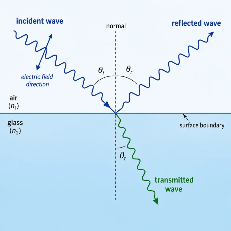
Reflection occurs when part of an electromagnetic wave bounces back from a surface or boundary. Transmission occurs when part of the wave passes into or through another material. In many real situations, a wave is not simply reflected or transmitted completely. Instead, part of its energy may be reflected, part transmitted, and part absorbed.
This page helps students see polarisation, reflection, and transmission as connected ideas. They are not separate tricks of light. They are ways electromagnetic waves interact with materials, surfaces, and fields.
Learning Pathway
This page completes the Electromagnetic Waves cluster by showing how waves behave when they meet surfaces, filters, and materials. It connects Maxwell’s wave picture, the electromagnetic spectrum, and wave energy transfer to real optical and communication systems.
Electricity and Magnetism
Introduces electric fields, magnetic fields, circuits, induction, and electromagnetic waves as connected parts of classical electromagnetism.Electromagnetic Waves
Explains how changing electric and magnetic fields form waves that can carry energy and information through space.Maxwell’s Equations and Electromagnetic Waves
Shows how Maxwell’s equations predict electromagnetic waves travelling through vacuum at the speed of light.Electromagnetic Spectrum
Arranges radio waves, microwaves, infrared, visible light, ultraviolet, X-rays, and gamma rays into one continuous electromagnetic family.Energy and Momentum in Electromagnetic Waves
Explores how electromagnetic waves carry energy, exert radiation pressure, and transfer momentum to matter.Polarisation, Reflection, and Transmission
Focuses on how electromagnetic waves are oriented, reflected, transmitted, filtered, and controlled by materials and surfaces.Core Physical Idea
The core idea is that electromagnetic waves have both direction of travel and field orientation. The direction of travel tells us where the wave is going. The electric field direction tells us how the wave is polarised.
For a plane electromagnetic wave, the electric field, magnetic field, and direction of travel are mutually perpendicular. If the wave travels forward, the electric field may oscillate vertically, horizontally, or at some other angle. That electric field orientation is the wave’s polarisation.
When the wave meets a surface or polarising material, its orientation may matter. A polarising filter may transmit one electric field direction while blocking another. A reflective surface may reflect one polarisation more strongly than another. At a boundary, the wave’s direction and amplitude may change depending on the material properties and angle of incidence.
Pictorial Illustration 1: Polarisation as Electric Field Direction
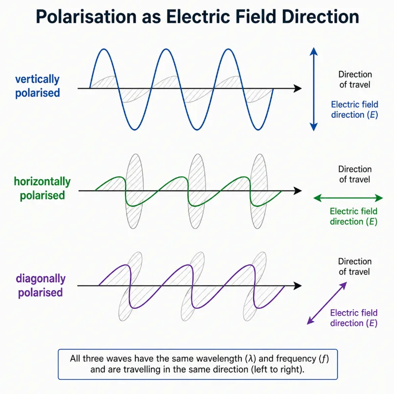
This illustration compares three electromagnetic waves travelling in the same direction with the same wavelength and frequency. The first wave is vertically polarised, the second is horizontally polarised, and the third is diagonally polarised. In each case, the electric field direction is highlighted with a clear arrow. The picture helps students understand that waves can move in the same direction and still differ in polarisation because their electric fields oscillate in different directions.
Key Equations and What They Mean
\( \theta_i = \theta_r \)
This is the law of reflection. The angle of incidence \( \theta_i \) equals the angle of reflection \( \theta_r \), measured from the normal line to the surface.
\( n_1 \sin \theta_1 = n_2 \sin \theta_2 \)
This is Snell’s law. It describes how the direction of a transmitted wave changes when it passes from one medium into another with a different refractive index.
\( I = I_0 \cos^2 \theta \)
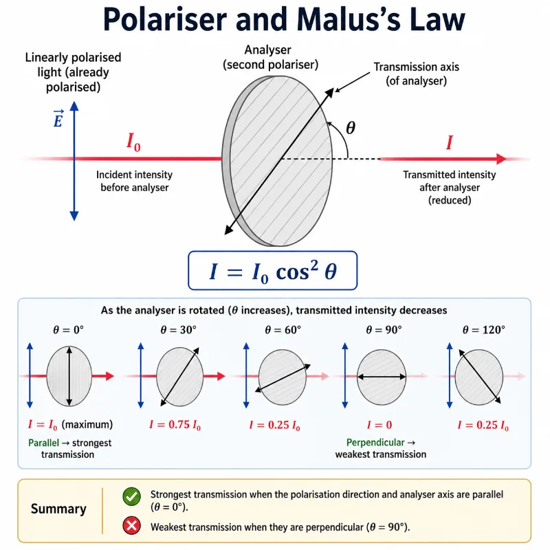
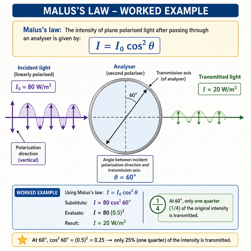
This is Malus’s law for ideal linear polarisers. \( I_0 \) is the intensity of light after the first polariser or before the analyser, \( I \) is the transmitted intensity, and \( \theta \) is the angle between the light’s polarisation direction and the transmission axis of the analyser.
\( \tan \theta_B = \frac{n_2}{n_1} \)
This is Brewster’s law for light incident from medium 1 into medium 2. At the Brewster angle \( \theta_B \), reflected light is strongly linearly polarised.
\( R + T + A = 1 \)
This is a simple energy-fraction idea for a wave meeting a material. \( R \) represents the reflected fraction, \( T \) the transmitted fraction, and \( A \) the absorbed fraction. In real materials, energy may be divided among reflection, transmission, and absorption.
Polarisation: Why Orientation Matters
In ordinary unpolarised light, the electric field directions are mixed. The wave does not have one fixed electric field orientation over time. Many natural light sources, such as the Sun and ordinary lamps, produce light that is mostly unpolarised.
Linearly polarised light is different. Its electric field oscillates mainly along one direction. For example, the electric field may oscillate vertically while the wave travels horizontally. A vertical polariser would allow this light to pass more strongly than a horizontal polariser.
Polarisation is important because many devices and materials respond differently to different electric field directions. This is why polarised sunglasses reduce glare, why liquid crystal displays control light, why 3D glasses separate images, and why antennas work best when their orientation matches the polarisation of the incoming wave.
Unpolarised Light
The electric field directions are mixed. Ordinary sunlight and many lamps produce light that is not restricted to one electric field direction.Linearly Polarised Light
The electric field oscillates mainly along one straight direction. This is the simplest and most commonly introduced form of polarisation.Circularly Polarised Light
The electric field direction rotates as the wave travels. This form of polarisation is important in some communication systems, optical instruments, and advanced physics.Partially Polarised Light
The light has some preferred electric field direction, but is not perfectly polarised. Reflected light from surfaces is often partially polarised.Pictorial Illustration 2: Polariser and Malus’s Law
Reflection: When Waves Bounce from a Boundary
Reflection occurs when an electromagnetic wave meets a surface and part of the wave returns into the original medium. A mirror reflects visible light strongly. A metal surface can reflect radio waves and microwaves. Water, glass, polished stone, and road surfaces can reflect light in ways that produce glare.
The simplest rule for reflection is that the angle of incidence equals the angle of reflection. Both angles are measured from the normal, an imaginary line perpendicular to the surface.
Reflection is not only about direction. It also involves energy. Some surfaces reflect strongly, while others absorb or transmit much of the incoming radiation. The reflected fraction depends on the material, surface texture, angle of incidence, wavelength, and polarisation.
Smooth Reflection
A smooth surface reflects waves in an orderly direction. Mirrors, calm water, and polished metal surfaces can produce clear reflected images.Diffuse Reflection
A rough surface scatters reflected light in many directions. This allows us to see objects from many viewing angles.Partial Reflection
At many transparent boundaries, part of the wave reflects while part continues through the material. A glass window can both reflect and transmit light.Polarised Reflection
Reflected light can become partially polarised, especially from non-metallic surfaces such as water, glass, or roads.Transmission: When Waves Pass into or Through Materials
Transmission occurs when an electromagnetic wave passes into or through a material. Glass transmits much visible light. Air transmits radio waves, visible light, and many other forms of electromagnetic radiation. Optical fibres transmit light signals along narrow glass paths.
When a wave enters a new medium, its speed may change. If it enters at an angle, its direction may also change. This bending is called refraction and is described by Snell’s law.
Transmission is not always complete. Some radiation may be reflected at the boundary, some absorbed inside the material, and some transmitted through it. Different wavelengths may transmit differently, which is why materials can appear coloured, opaque, transparent, or selective.
Transparent Materials
Transparent materials transmit a large fraction of visible light, allowing objects behind them to be seen clearly.Translucent Materials
Translucent materials transmit light but scatter it, so objects behind them appear blurred.Opaque Materials
Opaque materials transmit little or no visible light. They may absorb or reflect most of the incoming radiation.Selective Transmission
Some materials transmit certain wavelengths while absorbing others. Colour filters and tinted glass work through selective transmission.Pictorial Illustration 3: Reflection and Transmission at a Boundary
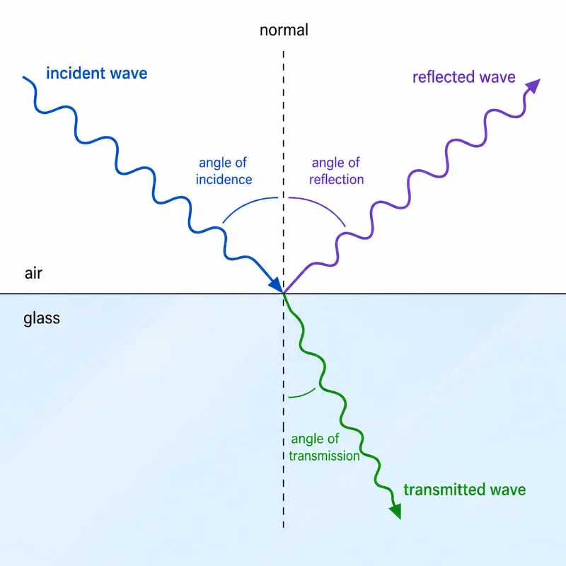
This illustration shows an incident electromagnetic wave travelling through air and striking a glass boundary. Part of the wave is reflected back into the air, while another part is transmitted into the glass and bends toward the normal. The diagram labels the normal, angle of incidence, angle of reflection, and angle of transmission, helping students understand how electromagnetic wave energy can be divided at a surface between reflection and transmission.
Why Polarisation Affects Reflection and Transmission
When light reflects from a non-metallic surface, the reflected wave may become partly polarised. This happens because the surface responds differently to different electric field orientations. At a special angle called Brewster’s angle, the reflected light can become strongly linearly polarised.
This is why polarised sunglasses can reduce glare from roads, water, and glass. Much of the glare from horizontal surfaces is horizontally polarised. A vertically oriented polarising filter blocks much of that reflected glare while allowing useful light to pass.
Polarisation also affects transmission. A polarising filter transmits the component of the electric field parallel to its transmission axis and reduces the perpendicular component. Two crossed polarisers can block most transmitted light.
Pictorial Illustration 4: Brewster’s Angle and Polarised Glare
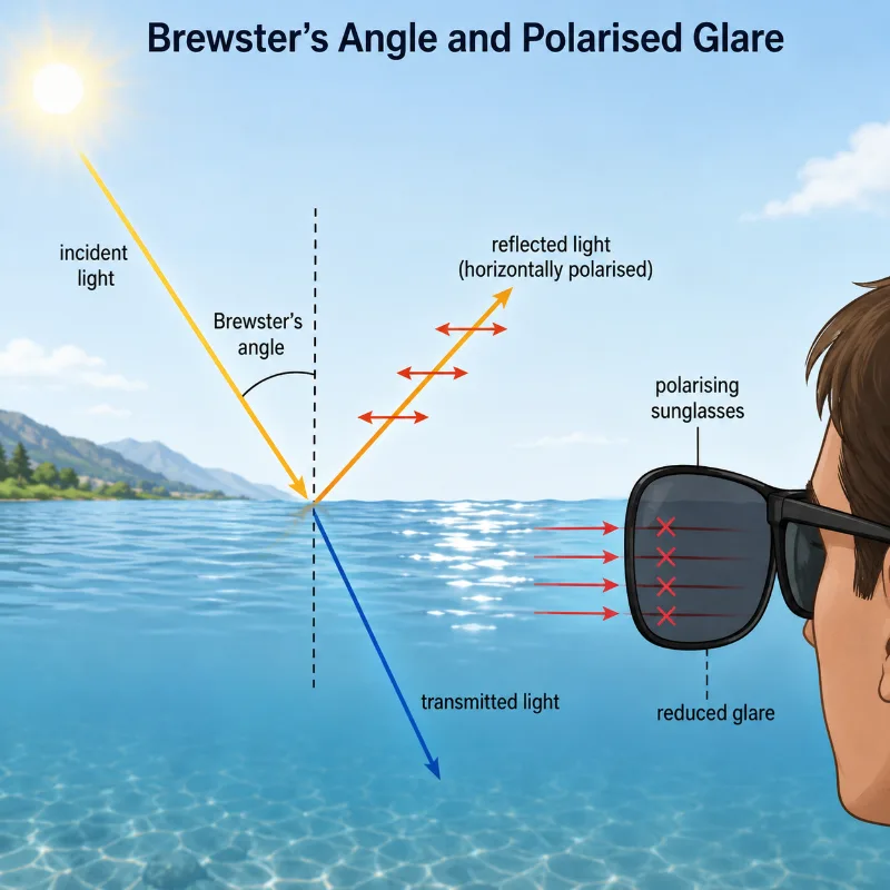
This illustration shows incident light striking a water surface at Brewster’s angle. Part of the light is transmitted into the water, while the reflected light becomes strongly horizontally polarised. A polarising sunglasses lens blocks much of this horizontally polarised glare before it reaches the eye. The picture helps students understand why glare from water, roads, and glass can be reduced by polarising filters.
Worked Example
Problem: Linearly polarised light of intensity \( I_0 = 80 \ \text{W/m}^2 \) passes through an analyser whose transmission axis makes an angle of \( 60^\circ \) with the light’s polarisation direction. Calculate the transmitted intensity.
Step 1: Write Malus’s law.
\( I = I_0 \cos^2 \theta \)
Step 2: Substitute the values.
\( I = 80 \cos^2 60^\circ \)
Step 3: Use \( \cos 60^\circ = 0.5 \).
\( I = 80(0.5)^2 \)
\( I = 80(0.25) \)
\( I = 20 \ \text{W/m}^2 \)
Answer: The transmitted intensity is \( 20 \ \text{W/m}^2 \).
Worked Example Illustration
Vector Projections: Deriving the Mechanics of Malus’s Law
When students first look at Malus’s law (\(I = I_0 \cos^2 \theta\)), the squared term can seem mysterious. To understand where this mathematical format comes from, university physics looks past the abstract wave intensity to trace the actual electric field amplitude vector (\(\mathbf{E}\)).
Imagine a linearly polarized light wave hitting a polarizing filter. The incoming wave has a peak electric field amplitude vector \(\mathbf{E}_0\). When this field meets a filter whose transmission axis is tilted at an angle \(\theta\), the filter breaks the incoming vector down into two perpendicular components. It completely absorbs or blocks the component perpendicular to its axis, while allowing the parallel component to pass smoothly through:
$$ E_{\text{transmitted}} = E_0 \cos\theta $$This simple cosine projection gives us the amplitude of the newly transmitted electric wave. However, we measure light in terms of intensity (\(I\)), which tracks the real physical power delivered per unit area. In wave mechanics, the total intensity carried by a wave is always directly proportional to the square of its field amplitude (\(I \propto E^2\)):
$$ \frac{I_{\text{transmitted}}}{I_0} = \frac{(E_{\text{transmitted}})^2}{(E_0)^2} = \frac{(E_0 \cos\theta)^2}{E_0^2} $$Canceling out the initial amplitude terms fields reveals the definitive law:
$$ I_{\text{transmitted}} = I_0 \cos^2 \theta $$This short vector projection proof shows students that the squared cosine term is a natural geometric consequence of transforming a vector field amplitude into a scalar energy footprint.
Advanced Field Continuity: The Foundations of the Fresnel Equations
In basic physics, we track how a wave changes direction using angles and index scales. At the university engineering level, we ask a deeper question: Exactly how much wave energy reflects back, and how much passes through? Finding these exact ratios requires analyzing how the electric and magnetic fields match up right at the boundary interface.
When an electromagnetic wave travels from air into glass, it hits a sharp boundary. Because energy must be conserved, the fields on the air side must smoothly match the fields on the glass side without any sudden breaks. These physical requirements are known as boundary conditions, derived directly from Maxwell’s equations:
- The parallel components of the electric field vector must be identical on both sides of the boundary line (\(E_{\text{incident}}^{\parallel} + E_{\text{reflected}}^{\parallel} = E_{\text{transmitted}}^{\parallel}\)).
- The parallel components of the magnetic field intensity vector must also match smoothly across the interface (\(H_{\text{incident}}^{\parallel} + H_{\text{reflected}}^{\parallel} = H_{\text{transmitted}}^{\parallel}\)).
By setting up these matching balance equations and sorting them by polarization orientation (whether the electric field oscillates parallel to the boundary or perpendicular to it), physicists derive the Fresnel Equations. For a wave hitting a surface straight on (normal incidence), these field continuity models simplify into an elegant scale ratio:
$$ R_{\text{amplitude}} = \frac{n_1 – n_2}{n_1 + n_2} \quad \text{and} \quad T_{\text{amplitude}} = \frac{2n_1}{n_1 + n_2} $$Squaring these amplitude terms gives engineers the exact power reflection coefficient (\(R = R_{\text{amplitude}}^2\)). For a standard air-to-glass interface (\(n_1 = 1.0\) and \(n_2 = 1.5\)), plugging in the numbers shows that exactly \(4\%\) of the incoming light intensity bounces back as a reflection, while the remaining \(96\%\) transmits safely through. This advanced look teaches students that the optical behaviors we see around us are governed by strict vector continuity laws at the material interface.
Common Misconceptions about Polarisation, Reflection, and Transmission
These topics can be confusing because students often treat electromagnetic waves as simple arrows or rays. Rays are useful, but they do not show the electric field orientation, wave amplitude, or energy division at a boundary.
Misconception 1: Polarisation Means the Wave Travels in a Different Direction
Polarisation does not describe the direction of travel. It describes the direction in which the electric field oscillates.Misconception 2: A Polariser Simply Makes Light Dimmer
A polariser does reduce intensity, but it does so selectively by transmitting certain electric field orientations more strongly than others.Misconception 3: Reflection Always Means All the Light Bounces Back
At many boundaries, only part of the light reflects. The rest may transmit into the second material or be absorbed.Misconception 4: Transmission Means the Wave Is Unchanged
A transmitted wave may change speed, wavelength, direction, intensity, or polarisation depending on the material and angle of incidence.Misconception 5: Polarised Sunglasses Block All Light
Polarised sunglasses mainly reduce glare from certain reflected light directions. They do not block all light equally.Misconception 6: Reflection and Refraction Are Only Visible-Light Effects
Radio waves, microwaves, infrared radiation, ultraviolet radiation, X-rays, and other electromagnetic waves can also reflect, transmit, scatter, absorb, or refract under suitable conditions.Practical Applications
Polarisation, reflection, and transmission are not only textbook ideas. They are used to control light, reduce glare, transmit information, analyse materials, image hidden structures, and observe the world more clearly.
Polarised Sunglasses
Polarised lenses reduce glare from roads, water, and glass by blocking much of the horizontally polarised reflected light.Liquid Crystal Displays
LCD screens use polarisation and controlled material response to regulate how much light reaches the viewer.Optical Fibre Communication
Light signals are transmitted through glass fibres by repeated internal reflection, allowing fast data transfer over long distances.Photography and Imaging
Polarising filters reduce reflections, deepen sky contrast, and help photographers control glare and surface shine.Remote Sensing
Reflected and transmitted electromagnetic waves reveal information about land, oceans, clouds, vegetation, ice, and built environments.Material Analysis
Polarised light and reflected radiation can reveal stress patterns, surface properties, crystal structures, and hidden defects.Antenna Alignment
Radio and microwave antennas work best when their orientation matches the polarisation of the transmitted or received wave.Medical and Scientific Instruments
Many imaging and measurement systems depend on how waves reflect, transmit, absorb, or change polarisation when interacting with matter.Real-World Illustration
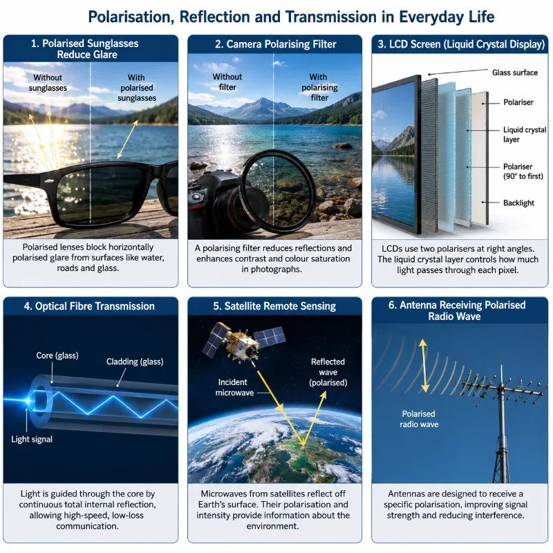
This illustration shows real-world uses of polarisation, reflection, and transmission in modern technology. Polarised sunglasses reduce reflected glare, camera polarising filters control reflections, LCD screens use polarisation to form images, optical fibres guide light signals, satellites detect reflected electromagnetic waves from Earth, and antennas receive polarised radio waves. The picture helps students see that electromagnetic wave behaviour is not only a classroom idea, but a foundation for everyday devices and scientific instruments.
Bridge to University Thinking
At school level, students often learn simple laws such as \( \theta_i = \theta_r \), \( n_1 \sin \theta_1 = n_2 \sin \theta_2 \), and \( I = I_0 \cos^2 \theta \). At university level, these ideas become part of a deeper wave picture.
Students learn that reflection and transmission come from boundary conditions on electric and magnetic fields. Polarisation becomes a vector property of electromagnetic waves. Optical materials are described through refractive index, absorption, anisotropy, birefringence, and sometimes complex permittivity.
This makes the topic a bridge between ray optics, wave optics, electromagnetism, materials science, photonics, remote sensing, and communication engineering.
From Rays to Fields
A simple light ray becomes a wave with electric and magnetic fields that must satisfy boundary conditions.From Brightness to Intensity
Qualitative brightness becomes measurable intensity, energy flow, and power per unit area.From Filters to Vector Components
A polariser becomes a device that selects a component of the electric field along a chosen axis.From Reflection to Fresnel Equations
Simple reflection becomes a quantitative study of how amplitude and intensity depend on angle, material, and polarisation.Quick Interactive Check
Quick Check: Polarisation, Reflection, and Transmission
1. What does polarisation describe in an electromagnetic wave?
A. The direction of wave travel
B. The colour of the wave only
C. The direction of electric field oscillation
D. The speed of the wave in vacuum
Answer: C. Polarisation describes the direction in which the electric field oscillates.
2. What is the law of reflection?
A. \( \theta_i = \theta_r \)
B. \( I = I_0 \cos^2 \theta \)
C. \( E = hf \)
D. \( c = f\lambda \)
Answer: A. The law of reflection states that the angle of incidence equals the angle of reflection.
3. Which equation gives the transmitted intensity through an analyser for linearly polarised light?
A. \( n_1 \sin \theta_1 = n_2 \sin \theta_2 \)
B. \( I = I_0 \cos^2 \theta \)
C. \( \lambda = \frac{c}{f} \)
D. \( F = qvB \)
Answer: B. Malus’s law is \( I = I_0 \cos^2 \theta \).
4. What can happen when light reaches a glass surface?
A. It must be fully absorbed
B. It must fully disappear
C. It may be partly reflected and partly transmitted
D. It can no longer be electromagnetic radiation
Answer: C. At many boundaries, part of the wave is reflected while another part is transmitted.
Review Questions and Answers
1. What is polarisation?
Polarisation describes the direction in which the electric field of an electromagnetic wave oscillates.
2. Why can electromagnetic waves be polarised?
Electromagnetic waves are transverse waves. Their electric and magnetic fields oscillate perpendicular to the direction of travel, so the electric field can have a particular orientation.
3. What is the law of reflection?
The angle of incidence equals the angle of reflection, measured from the normal line to the surface.
4. What is transmission?
Transmission occurs when an electromagnetic wave passes into or through a material.
5. What is refraction?
Refraction is the change in direction that occurs when a wave enters a different medium at an angle and changes speed.
6. What does Malus’s law describe?
Malus’s law describes how the intensity of linearly polarised light changes when it passes through an analyser at an angle.
7. Why do polarised sunglasses reduce glare?
They block much of the reflected light that is polarised in a particular direction, especially glare from horizontal surfaces.
8. What happens at Brewster’s angle?
At Brewster’s angle, reflected light from a non-metallic surface becomes strongly linearly polarised.
9. Can waves be both reflected and transmitted at the same boundary?
Yes. At many boundaries, part of the wave reflects while part is transmitted into the second medium.
10. Why is polarisation important in technology?
Polarisation is used in sunglasses, displays, cameras, optical instruments, antennas, remote sensing, and communication systems.
Thought-Provoking Questions and Answers
1. Why is polarisation strong evidence that electromagnetic waves are transverse?
Only transverse waves can have a sideways orientation that can be filtered by direction. Since electromagnetic waves can be polarised, their fields must oscillate perpendicular to their direction of travel.
2. Why can a transparent window both reflect and transmit light?
At the air-glass boundary, the electromagnetic wave interacts with charges in the material. Part of the wave energy can return as reflection, while part continues into the glass as transmission.
3. Why does a polarising filter not simply block half of all light in every situation?
The effect depends on the incoming light’s polarisation state. Unpolarised light, linearly polarised light, and partially polarised reflected light behave differently when they pass through a polariser.
4. Why does the orientation of an antenna matter?
An antenna responds to the electric field direction of an incoming electromagnetic wave. If the antenna is poorly aligned with the wave’s polarisation, the received signal may be weaker.
5. Why are reflection and transmission more complex than simple ray diagrams suggest?
Ray diagrams show direction, but the full wave picture also includes electric field orientation, magnetic field orientation, amplitude, phase, energy flow, absorption, and material response.
Numerical Problems and Solutions
Problem 1: Linearly polarised light of intensity \( 100 \ \text{W/m}^2 \) passes through an analyser at an angle of \( 30^\circ \) to the polarisation direction. Find the transmitted intensity.
Solution:
\( I = I_0 \cos^2 \theta \)
\( I = 100 \cos^2 30^\circ \)
\( \cos 30^\circ = 0.866 \)
\( I = 100(0.866)^2 \)
\( I \approx 75 \ \text{W/m}^2 \)
The transmitted intensity is approximately \( 75 \ \text{W/m}^2 \).
Problem 2: Linearly polarised light of intensity \( 60 \ \text{W/m}^2 \) passes through an analyser at \( 90^\circ \). Find the transmitted intensity.
Solution:
\( I = I_0 \cos^2 \theta \)
\( I = 60 \cos^2 90^\circ \)
\( \cos 90^\circ = 0 \)
\( I = 0 \)
The transmitted intensity is \( 0 \ \text{W/m}^2 \) for ideal crossed polarisation.
Problem 3: A light ray strikes a mirror at an angle of incidence of \( 40^\circ \). What is the angle of reflection?
Solution:
By the law of reflection:
\( \theta_i = \theta_r \)
\( \theta_r = 40^\circ \)
The angle of reflection is \( 40^\circ \).
Problem 4: Light travels from air into glass. If \( n_1 = 1.00 \), \( n_2 = 1.50 \), and \( \theta_1 = 30^\circ \), find the angle of refraction \( \theta_2 \).
Solution:
\( n_1 \sin \theta_1 = n_2 \sin \theta_2 \)
\( 1.00 \sin 30^\circ = 1.50 \sin \theta_2 \)
\( 0.5 = 1.50 \sin \theta_2 \)
\( \sin \theta_2 = \frac{0.5}{1.50} = 0.333 \)
\( \theta_2 \approx 19.5^\circ \)
The angle of refraction is approximately \( 19.5^\circ \).
Problem 5: Light travels from air into glass with \( n_1 = 1.00 \) and \( n_2 = 1.50 \). Find Brewster’s angle.
Solution:
\( \tan \theta_B = \frac{n_2}{n_1} \)
\( \tan \theta_B = \frac{1.50}{1.00} = 1.50 \)
\( \theta_B = \tan^{-1}(1.50) \)
\( \theta_B \approx 56.3^\circ \)
Brewster’s angle is approximately \( 56.3^\circ \).
Problem 6: At a surface, \( 30\% \) of the incident wave energy is reflected and \( 60\% \) is transmitted. What percentage is absorbed?
Solution:
\( R + T + A = 1 \)
\( 0.30 + 0.60 + A = 1 \)
\( A = 0.10 \)
The absorbed fraction is \( 10\% \).
Summary
Polarisation describes the orientation of the electric field in an electromagnetic wave. Because electromagnetic waves are transverse waves, their electric fields can oscillate in particular directions.
Reflection occurs when part of a wave returns from a surface or boundary. Transmission occurs when part of the wave passes into or through another material. In many real situations, reflection, transmission, and absorption occur together.
Polarisation affects how waves interact with filters, surfaces, antennas, crystals, screens, optical devices, and materials. Malus’s law describes transmission through a polariser, while Brewster’s law explains a special angle at which reflected light becomes strongly polarised.
These ideas are important in everyday life and advanced technology, including sunglasses, displays, photography, optical fibres, remote sensing, antennas, communication systems, and scientific imaging.
Glossary
Polarisation: The orientation of the electric field oscillation in an electromagnetic wave.
Unpolarised light: Light whose electric field directions are mixed rather than fixed along one direction.
Linearly polarised light: Light whose electric field oscillates mainly along one straight direction.
Polariser: A device or material that transmits one electric field direction more strongly than another.
Analyser: A polariser used to test or measure the polarisation state of incoming light.
Reflection: The return of part of a wave from a surface or boundary.
Transmission: The passage of a wave into or through a material.
Refraction: The bending of a wave when it enters a different medium and changes speed.
Brewster’s angle: The angle of incidence at which reflected light from a non-metallic surface becomes strongly linearly polarised.
Malus’s law: The law \( I = I_0 \cos^2 \theta \), which describes how transmitted intensity depends on the angle between polarisation direction and analyser axis.
Frequently Asked Questions
1. What is polarisation in simple terms?
Polarisation is the direction in which the electric field of an electromagnetic wave oscillates.
2. Why can electromagnetic waves be polarised?
They can be polarised because they are transverse waves. Their electric and magnetic fields oscillate perpendicular to the direction of travel.
3. What is the difference between reflection and transmission?
Reflection means part of the wave returns from a surface, while transmission means part of the wave passes into or through a material.
4. Does a polariser block all light except one direction?
An ideal polariser transmits the electric field component along its transmission axis and blocks or absorbs much of the perpendicular component.
5. What does Malus’s law tell us?
Malus’s law tells us how the transmitted intensity of linearly polarised light depends on the angle between the light’s polarisation direction and the analyser axis.
6. Why do polarised sunglasses reduce glare?
They reduce glare because much reflected light from horizontal surfaces is polarised in a direction that the sunglasses are designed to block.
7. What happens at Brewster’s angle?
At Brewster’s angle, reflected light from a non-metallic surface is strongly linearly polarised.
8. Are reflection and transmission only important for visible light?
No. Many electromagnetic waves, including radio waves, microwaves, infrared radiation, and X-rays, can reflect, transmit, absorb, or scatter depending on the material and wavelength.