
Overhang Limits and Support Generation Physics in Additive Manufacturing
Analytical Mechanics of Layer Stacking, Melt Pool Heat Sinking & Support Architectures
Core Competencies Learned
- Derive the geometric critical overhang angle \(\theta_c\) as a function of bead width-to-height aspect ratio (\(W/H\)) and minimum structural contact overlap.
- Model 1D conductive heat transfer through supports in Laser Powder Bed Fusion (PBF/DMLS) to prevent thermal accumulation, residual stress curling, and dross formation.
- Evaluate techno-economic trade-offs between linear accordion walls, cellular block lattices, and organic tree support architectures.
In layer-by-layer additive manufacturing, gravity and thermal accumulation impose physical boundaries on geometry. When a newly deposited molten polymer bead or melted metal pool extends horizontally beyond the boundary of the underlying layer, it forms an overhang. Without sufficient mechanical overlap or adequate thermal heat dissipation, the unsupported phase droops under gravity, creates extensive dross, or curls upward due to asymmetric thermal contraction. This module details the vector mechanics, thermodynamics, and structural algorithms that define support generation in modern AM.
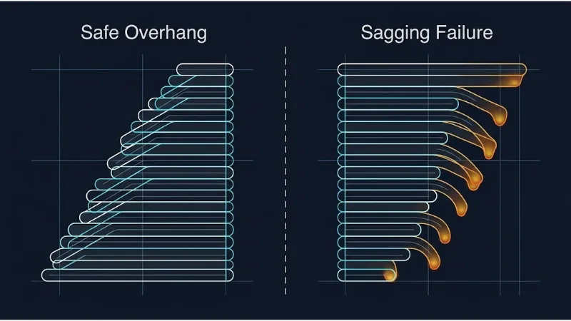
Figure 1: Bead stacking mechanics. Left: Safe overhang with consistent bead-on-bead contact area. Right: Unstable overhang where excessive horizontal step offsets cause molten bead droop and dimensional failure.
Support Generation Architecture (IDEF0 Analysis)
To analyze support placement as a deterministic systems engineering process, we map its four functional boundaries:
1. Geometric Mechanics: The Derivation of the Critical Overhang Angle
Consider an extrusion-based process (Material Extrusion / MEX / FDM) depositing a bead with nominal width \(W\) and layer thickness \(H\). When an edge is tilted relative to the vertical build axis \(Z\) by an overhang angle \(\theta\), successive layers shift horizontally by a step distance \(\Delta x\):
$$ \Delta x = H \tan(\theta) $$The shared contact width \(W_{overlap}\) between layer \(k\) and layer \(k-1\) is given by the difference between the bead width and the horizontal step:
$$ W_{overlap} = W - \Delta x = W - H \tan(\theta) $$To maintain mechanical equilibrium while the polymer is in its viscous, molten state (above the glass transition temperature \(T_g\)), the center of mass of the newly deposited bead must remain supported by the underlying layer. This requires an overlap ratio \(\eta = W_{overlap} / W \ge \eta_{min}\), where empirical manufacturing standards require \(\eta_{min} \approx 0.50\) (the 50% overlap rule):
$$ W - H \tan(\theta_c) = \eta_{min} W \quad \Rightarrow \quad H \tan(\theta_c) = (1 - \eta_{min}) W $$Solving explicitly for the theoretical critical overhang angle \(\theta_c\) (measured from the vertical \(Z\)-axis):
$$ \theta_c = \arctan\left( (1 - \eta_{min}) \frac{W}{H} \right) $$For standard 3D printing configurations where nozzle diameter produces \(W = 0.40\text{ mm}\), layer thickness is set to \(H = 0.20\text{ mm}\) (aspect ratio \(W/H = 2.0\)), and \(\eta_{min} = 0.50\):
$$ \theta_c = \arctan\left( (1 - 0.50) \times 2.0 \right) = \arctan(1.0) = 45^\circ $$If \(\theta > \theta_c\), the unsupported outer fraction of the molten bead creates an unbalanced gravitational torque about the support edge. Viscous surface tension cannot resist gravity, causing the molten filament to sag downward and form hanging loops or dimensional delamination.
Worked Example: Calculating Critical Angle Under Varying Layer Heights
Problem: An engineer switches an extrusion nozzle from a standard layer thickness of \(H = 0.28\text{ mm}\) to a fine-resolution setting of \(H = 0.12\text{ mm}\) while keeping the bead width fixed at \(W = 0.45\text{ mm}\). Assuming a minimum allowable bead overlap of \(\eta_{min} = 0.40\), calculate the shift in the critical overhang angle \(\theta_c\).
Step 1: Calculate \(\theta_{c1}\) for coarse resolution (\(H_1 = 0.28\text{ mm}\))
$$ \frac{W}{H_1} = \frac{0.45}{0.28} \approx 1.607 $$ $$ \theta_{c1} = \arctan\left( (1 - 0.40) \times 1.607 \right) = \arctan(0.60 \times 1.607) = \arctan(0.9643) \approx 43.96^\circ $$Step 2: Calculate \(\theta_{c2}\) for fine resolution (\(H_2 = 0.12\text{ mm}\))
$$ \frac{W}{H_2} = \frac{0.45}{0.12} = 3.75 $$ $$ \theta_{c2} = \arctan\left( (1 - 0.40) \times 3.75 \right) = \arctan(0.60 \times 3.75) = \arctan(2.25) \approx 66.04^\circ $$2. Thermal Physics: Supports as Conductive Heat Sinks in Metal AM
While polymer extrusion requires supports primarily to counteract gravity, Powder Bed Fusion (PBF/DMLS/SLM) requires supports for thermal management. Loose, unsintered metal powder has poor thermal conductivity because particle-to-particle point contacts are separated by void gas:
$$ k_{powder} \approx 0.01 \text{ to } 0.02 \times k_{solid} $$When a laser beam melts metal directly over loose powder, heat accumulates within the melt pool. The heat cannot conduct downward through the insulating powder bed, causing steep thermal gradients and severe failure modes:
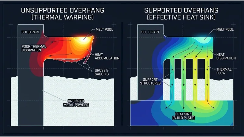
Figure 2: Thermal mechanics in Powder Bed Fusion. Left: Heat traps above insulating powder, triggering melt-pool enlargement, upward curling, and heavy dross. Right: Solid supports provide a low-resistance conduction path directly into the build plate heatsink.
Conductive heat dissipation through a support structure of cross-sectional area \(A_s\), height \(L_s\), and solid thermal conductivity \(k_s\) is governed by Fourier's Law of Thermal Conduction:
$$ q = -k_s A_s \frac{dT}{dz} \approx k_s A_s \frac{T_{melt} - T_{plate}}{L_s} $$If the heat flow \(q\) through the supports is insufficient to dissipate the laser energy input, the local temperature remains above the solidus point for too long. Liquid metal infiltrates surrounding powder particles via capillary forces, forming a rough, jagged under-surface known as dross. As cooling eventually occurs, extreme thermal shrinkage strains (\(\varepsilon_{th} = \alpha \Delta T\)) induce plastic deformation that curls the overhang upward, causing the recoater blade to collide with the part and abort the build.
3. Support Typologies and Algorithmic Extraction
Modern slicing engines implement three primary geometric support structures, each tailored to specific manufacturing and post-processing constraints:
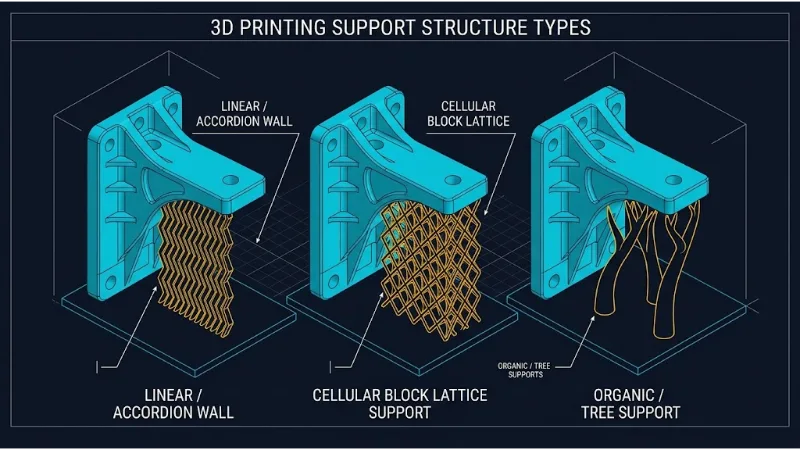
Figure 3: Support architectures. Left: Linear accordion wall. Center: Cellular block lattice. Right: Organic tree support with branching pillars and tapered contact interfaces.
1. Linear / Accordion Walls: Continuous vertical ribbons patterned in a zigzag wave. They provide high mechanical stiffness against buckling, but require extensive post-print chiseling or machining and leave witness marks across the entire supported surface.
2. Cellular Block Lattices: Open-cell diamond or octet truss matrices. Widely utilized in metal PBF, these lattices provide high axial compressive strength and stable heat sinking while enabling un-sintered powder to drain freely during depowdering.
3. Organic / Tree Supports: Algorithmic, branching skeletons generated via 3D Voronoi or Dijkstra path-routing graphs. Tree supports route around complex geometry, growing upward from the build plate to touch down exclusively at necessary overhang points. Tapered needle tips minimize the contact surface area, enabling manual breakaway without surface scarring.
4. Interactive Overhang Stability & Heat Dissipation Simulator
Adjust the geometric and process variables below to simulate layer step offset, bead-on-bead contact percentage, and thermal dissipation status in real time.
5. Trade-Off Analysis: Support Architecture Strategies
Selecting support parameters requires balancing print time, raw material consumption, surface finish quality, and manual post-processing complexity:
| Support Topology | Primary Engineering Advantage | Key Technical Bottleneck | Mitigation Strategy |
|---|---|---|---|
| Linear Accordion Walls | Maximum structural rigidity against transverse recoater shear forces. | High material consumption; difficult manual breakout leaving continuous scars. | Implement perforated 1-layer separation interface gaps (\(\Delta z_{gap} = 1\times H\)). |
| Cellular Block Lattices | High thermal heat sink capacity; enables un-sintered powder evacuation in PBF. | High computational slicing overhead; potential powder trapping in closed cells. | Utilize gyroid or open diamond TPMS topologies with pore sizes \( > 1.5\text{ mm} \). |
| Organic / Tree Supports | Minimal contact surface scarring; 40–70% reduction in support material volume. | Low lateral stiffness; susceptible to vibrational resonance and mechanical buckling. | Apply branch trunk merging algorithms and limit unsupported branch length-to-diameter ratios. |
6. Overhang Limits & Support Physics FAQ
Q1: Why is 45° widely cited as the universal critical overhang threshold?
The 45° threshold is derived from standard extrusion geometry where the bead width-to-height aspect ratio is roughly \(W/H \approx 2.0\). At 45°, the horizontal step offset equals the layer height (\(\Delta x = H\)), which naturally leaves exactly 50% of the bead supported by the underlying layer. This 50% overlap prevents the center of mass from tipping into free space.
Q2: What causes metal parts to curl upward rather than sag downward in unsupported PBF prints?
In Powder Bed Fusion, the temperature gradient mechanism (TGM) dominates. Laser heating rapidly expands the upper surface of the molten layer while cooler material below restricts expansion. Upon cooling, the top surface undergoes extreme thermal shrinkage contraction. Because the lower region is unanchored to a rigid base plate, asymmetric tension forces the cantilevered edges to curl upward.
Q3: How does the thermal conductivity of unsintered powder compare to solid bulk metal?
Loose metal powder exhibits an effective thermal conductivity that is only 1% to 2% of the equivalent solid metal. The presence of argon or nitrogen gas in the inter-particle voids acts as a thermal insulator, preventing heat dissipation and necessitating solid metallic support structures to channel thermal energy into the build plate.
Q4: What is the mechanical role of the Z-interface gap in break-away supports?
The Z-interface gap is an unprinted vertical offset (typically 1 to 2 layer heights, e.g., 0.15–0.25 mm) intentionally introduced between the top of the support structure and the bottom surface of the part. This small spatial gap allows radiated cooling to freeze the underside bead before it can chemically coalesce with the support, enabling manual break-away removal.
Q5: How do organic tree supports prevent mechanical buckling during high-speed printing?
Tree supports mitigate column buckling by implementing branching algorithms that fuse adjacent limbs into common structural trunks. Slicers apply Euler's critical column buckling formulas, increasing trunk diameter dynamically as vertical build height increases to resist lateral shear loads caused by printhead acceleration.
Q6: Can bridging geometry exceed the critical overhang angle without supports?
Yes. Horizontal spans anchored at both ends (bridges) operate under tensile catenary dynamics rather than unsupported cantilever dynamics. When spanning between two solid pillars, slicers increase extrusion speed, decrease material flow, and run cooling fans at 100% to freeze the filament strand in mid-air under tension.
7. Overhang Limits & Support Physics Self-Assessment
Tier 1: Foundational Practice (True/False & Concept Recall)
Q1.1: If an overhang angle is measured from the horizontal plane, does a larger angle indicate a steeper vertical wall or a flatter ledge?
Q1.2: True or False: Reducing layer height H without altering extrusion width W increases the allowable critical overhang angle.
Q1.3: What is the primary heat dissipation failure mechanism in unsupported Powder Bed Fusion overhangs?
Q1.4: True or False: Polymer tree supports consume more raw material than solid linear accordion walls on large planar horizontal ledges.
Q1.5: What parameter defines the physical gap left between support contact points and the model surface?
Q1.6: Why do circular internal horizontal holes frequently print successfully without supports?
Q1.7: What occurs during recoater blade collision in metal PBF?
Q1.8: What is the minimum theoretical bead overlap percentage required to keep an extrusion center of mass supported?
Tier 2: Applied Conceptual Cases & Process Debugging
Q2.1: Diagnosing severe roughness on downward-facing metal surfaces
Analysis: Heat accumulates at the downward-facing surfaces due to the insulating properties of the surrounding powder bed. The enlarged melt pool sinks into the powder. Increasing support density beneath these regions provides conductive pathways to the build plate, drawing heat away and stabilizing the melt pool boundary.
Q2.2: Mitigating support scars on precision optical surfaces
Analysis: Reorient the CAD geometry on the virtual build plate. Tilting the component so that critical functional surfaces maintain an overhang angle below 45° eliminates the need for supports entirely, transferring support placement to non-critical external surfaces.
Q2.3: Structural failure of slender tree supports during tall builds
Analysis: The long, slender columns succumb to mechanical vibration from printhead accelerations and Euler buckling loads. Mitigate by increasing the tree trunk diameter, lowering printhead travel acceleration, or enabling branch-branch cross-bracing in the slicer settings.
Q2.4: Managing thermal stress accumulation in large horizontal metal ledges
Analysis: High thermal shrinkage stresses exceed the tensile bond strength between the support interface and the substrate. Replace solid support blocks with cellular diamond lattice structures that can yield slightly to accommodate thermal strain while maintaining adequate heat conduction.
Q2.5: Preventing fused break-away interfaces in high-temperature polymers
Analysis: Chamber temperatures near the glass transition temperature (\(T_g\)) permit polymer chain diffusion across the vertical air gap. Increase the Z-interface gap, lower the interface extrusion temperature, or transition to a chemically dissimilar, soluble support material (such as high-temperature soluble polymers).
Q2.6: Slicing overhang thresholds on variable-layer-height models
Analysis: The critical overhang angle is an explicit function of layer height: \(\theta_c = \arctan((1-\eta)W/H)\). Tripling the layer height reduces \(\theta_c\) significantly. Slicers must evaluate support generation dynamically on a layer-by-layer basis rather than applying a single global angle threshold.
Q2.7: Depowdering blockages in complex internal lattice supports
Analysis: The cellular support lattice design did not account for fluid evacuation dynamics. Replace closed cell grids with open-cell TPMS structures (such as gyroids) and ensure drain holes are at least 3 mm to 5 mm in diameter to facilitate powder flow during vacuum or vibration cleaning.
Tier 3: Quantitative Numerical Engineering Problems
Q3.1: Deriving the maximum step displacement before tipping
Steps: 1. Minimum required overlap width: $$ W_{overlap} = 0.55 \times W = 0.55 \times 0.50\text{ mm} = 0.275\text{ mm} $$ 2. Maximum allowable step offset: $$ \Delta x_{max} = W - W_{overlap} = 0.50 - 0.275 = 0.225\text{ mm} $$ 3. Critical angle derivation: $$ \tan(\theta_c) = \frac{\Delta x_{max}}{H} = \frac{0.225\text{ mm}}{0.25\text{ mm}} = 0.90 \quad \implies \quad \theta_c = \arctan(0.90) \approx 41.99^\circ $$
Q3.2: Calculating 1D conductive heat flux through a PBF support strut
Steps: 1. Temperature differential: $$ \Delta T = 1400^\circ\text{C} - 100^\circ\text{C} = 1300\text{ K} $$ 2. Fourier's Law application: $$q = k_s A_s \frac{\Delta T}{L_s} = 15 \times (1.2 \times 10^{-6}) \times \frac{1300}{0.008}$$ $$q = 15 \times 1.2 \times 10^{-6} \times 162500 = 2.925\text{ W}$$
Q3.3: Evaluating volumetric support savings with organic tree architectures
Steps: 1. Volume of linear support block: $$V_{envelope} = 30 \times 20 \times 60 = 36000\text{ mm}^3$$ $$V_{linear} = 0.20 \times 36000 = 7200\text{ mm}^3$$ 2. Volume of tree supports: $$A_{trunk} = \frac{\pi D^2}{4} = \frac{\pi (4)^2}{4} = 12.566\text{ mm}^2$$ $$V_{tree} = 4 \times (A_{trunk} \times L) = 4 \times (12.566 \times 65) = 3267.2\text{ mm}^3$$ 3. Percentage material savings: $$\text{Savings} = \frac{V_{linear} - V_{tree}}{V_{linear}} \times 100 = \frac{7200 - 3267.2}{7200} \times 100 \approx 54.62\%$$
Q3.4: Estimating thermal contraction curling stress on a cantilever ledge
Steps: 1. Thermal strain calculation: $$\varepsilon_{th} = \alpha \Delta T = (8.6 \times 10^{-6}\text{ K}^{-1}) \times 650\text{ K} = 5.59 \times 10^{-3}$$ 2. Thermal stress under full mechanical constraint: $$\sigma_{th} = E \times \varepsilon_{th} = (110 \times 10^9\text{ Pa}) \times (5.59 \times 10^{-3}) = 614.9 \times 10^6\text{ Pa} \approx 615\text{ MPa}$$
Q3.5: Calculating critical column buckling load on a slender tree support
Steps: 1. Area moment of inertia for circular cross-section: $$I = \frac{\pi d^4}{64} = \frac{\pi (0.0035)^4}{64} \approx 7.366 \times 10^{-12}\text{ m}^4$$ 2. Effective column length: $$L_e = K L = 0.7 \times 0.12 = 0.084\text{ m}$$ 3. Critical buckling load: $$P_{cr} = \frac{\pi^2 E I}{L_e^2} = \frac{\pi^2 \times (2.4 \times 10^9) \times (7.366 \times 10^{-12})}{(0.084)^2}$$ $$P_{cr} = \frac{0.1745}{0.007056} \approx 24.73\text{ N}$$
Q3.6: Calculating nozzle deposition speed adjustments for bridging spans
Steps: 1. Standard bead cross-sectional area: $$A_{std} = \frac{Q_{std}}{V_{std}} = \frac{4.0\text{ mm}^3\text{/s}}{50\text{ mm/s}} = 0.080\text{ mm}^2$$ 2. Bridging volumetric flow rate: $$Q_{bridge} = 0.80 \times 4.0 = 3.2\text{ mm}^3\text{/s}$$ 3. Bridging strand cross-sectional area: $$A_{bridge} = \frac{Q_{bridge}}{V_{bridge}} = \frac{3.2\text{ mm}^3\text{/s}}{65\text{ mm/s}} \approx 0.0492\text{ mm}^2$$
Interactive Education Hub Navigation
Continue exploring the Additive Manufacturing series across related computational and hardware modules:
Slicing Mathematics & Toolpaths
Learn the vector math of STL facet-plane intersections and Ray-Casting parity rules that feed toolpaths into support generators.
Overhang Limits & Support Physics
Analytical mechanics of layer stacking, thermal heat sinking in powder beds, and support architecture trade-offs.
The ISO/ASTM 52900 7 Categories
Understand the energy-matter bonding mechanics across all seven standardized additive manufacturing process classifications.