
The 7 Types of Additive Manufacturing: Principles of ISO/ASTM 52900
Consolidation Thermodynamics, Energy-Matter Coupling & Industrial Taxonomy
Core Competencies Learned
- Classify any additive system systematically into one of the 7 standardized ISO/ASTM 52900 categories based on initial feedstock state and physical consolidation mechanism.
- Model the analytical physics of primary consolidation regimes: Jacobs' photopolymerization equation (VPP), Rosenthal thermal moving melt pools (PBF/DED), and Young-Laplace capillary wetting (BJT).
- Evaluate techno-economic trade-offs between build volume rates, volumetric energy densities, residual thermal stress states, and post-processing furnace debinding/sintering cycles.
Additive manufacturing (AM) encompasses diverse physical phenomena, ranging from photon-driven monomer cross-linking to multi-kilowatt electron-beam thermal metallurgical melting. To establish international rigor across design, materials certification, and mechanical qualification, the ISO/ASTM 52900 standard establishes seven mutually exclusive, technologically comprehensive process categories. Rather than relying on commercial brand names, this standard classifies processes by their fundamental physics: feedstock state (liquid, powder, sheet, or solid filament) and the energy-matter consolidation mechanism. This module examines the theoretical models, governing thermodynamics, and engineering boundaries defining each category.
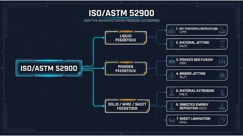
Figure 1: The ISO/ASTM 52900 taxonomy architecture. Additive manufacturing processes are systematically classified across feedstock phases and fundamental consolidation regimes.
Process Classification Engine (IDEF0 Analysis)
To analyze AM process selection as a deterministic systems engineering operation, we structure its functional boundaries:
1. Governing Physics of the 7 ISO/ASTM 52900 Process Categories
Each AM category relies on distinct governing physical equations to transform disorganized raw matter into a consolidated, dense solid structure:
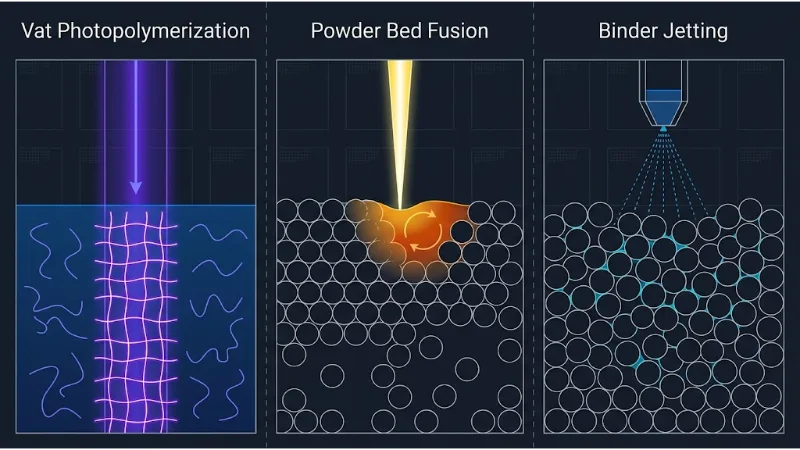
Figure 2: Microscopic consolidation physics across AM classes. (a) Free-radical cross-linking in liquid resins (VPP), (b) High-energy thermal melt pool conduction in metal powders (PBF), and (c) Capillary binder droplet necking between unbound particles (BJT).
1. Vat Photopolymerization (VPP)
VPP uses light-activated polymerization to selectively cure liquid photopolymer resin contained within a vat (e.g., SLA, DLP, CLIP). Light exposure follows the Beer-Lambert Law of Absorption, producing Jacobs' fundamental working curve for cure depth \(C_d\):
$$ C_d = D_p \ln\left( \frac{E_{max}}{E_c} \right) $$where \(D_p\) is the resin penetration depth (optical sensitivity parameter), \(E_{max}\) is the peak radiant energy exposure delivered to the resin surface (\(\text{mJ/cm}^2\)), and \(E_c\) is the critical gelation exposure threshold required to initiate gel transition.
2. Powder Bed Fusion (PBF)
PBF selectively fuses regions of a powder bed using thermal energy delivered by laser or electron beams (e.g., LPBF, SLM, SLS, EBM). The steady-state temperature field \(T(x,y,z)\) surrounding the moving beam spot is modeled using the Rosenthal Moving Point Heat Source Solution:
$$ T - T_0 = \frac{P \cdot \eta}{2\pi k R} \exp\left( -\frac{v (R + x)}{2\alpha} \right) $$where \(P\) is beam laser power, \(\eta\) is absorptivity, \(k\) is material thermal conductivity, \(\alpha\) is thermal diffusivity (\(\alpha = k / (\rho c_p)\)), \(v\) is scan velocity, and \(R = \sqrt{x^2 + y^2 + z^2}\) is radial distance from the beam center.
3. Material Extrusion (MEX)
MEX selectively dispenses material through a calibrated nozzle or orifice (e.g., FDM, FFF). Polymer molecules across adjacent deposited beads fuse via thermal diffusion and reptation dynamics across their interface. The degree of molecular healing \(U_{heal}\) depends on the time the interface remains above the glass transition temperature \(T_g\):
$$ U_{heal}(t) \propto \left( \int_0^t \frac{1}{\tau(T(t'))} \, dt' \right)^{1/4} $$where \(\tau(T)\) is the temperature-dependent polymer chain relaxation time governed by the Williams-Landel-Ferry (WLF) relation.
4. Binder Jetting (BJT)
BJT selectively deposits a liquid bonding agent onto a powder bed. Powder particles are drawn together without melting through capillary pressure \(P_c\) governed by the Young-Laplace equation:
$$ P_c = \frac{2\gamma_{LV} \cos(\theta)}{r_{pore}} $$where \(\gamma_{LV}\) is liquid-vapor surface tension, \(\theta\) is liquid contact angle, and \(r_{pore}\) is the inter-particle pore throat radius. The resulting "green body" requires post-process debinding and high-temperature furnace sintering to achieve solid density.
5. Material Jetting (MJT)
MJT deposits micro-droplets of build material (e.g., UV photopolymers, wax) through piezoelectric print arrays. Droplet stability during ejection is determined by the dimensionless Ohnesorge number \(Oh\):
$$ Oh = \frac{\mu}{\sqrt{\rho \gamma d_{nozzle}}} \quad \Rightarrow \quad 0.1 \le Oh \le 1.0 $$where \(\mu\) is liquid dynamic viscosity, \(\rho\) is density, \(\gamma\) is surface tension, and \(d_{nozzle}\) is orifice diameter. Droplets outside this stability envelope either fail to eject or break into erratic satellite mist.
6. Directed Energy Deposition (DED)
DED harnesses focused thermal energy (laser, electron beam, or electric plasma arc) to melt materials as they are deposited (e.g., LENS, EBAM, WAAM). The volumetric energy density \(E_v\) applied to the feed stream is expressed as:
$$ E_v = \frac{P}{v \cdot h_w \cdot t_l} $$where \(P\) is power, \(v\) is travel velocity, \(h_w\) is hatch spacing/bead width, and \(t_l\) is layer deposition height. DED exhibits deposition rates orders of magnitude higher than PBF, making it standard for large-scale structural components and component repair.
7. Sheet Lamination (SHL)
SHL bonds sheets of material (paper, metal foils, composites) to form a part (e.g., LOM, Ultrasonic Additive Manufacturing / UAM). In metal UAM, solid-state acoustic consolidation occurs via high-frequency ultrasonic vibrations (\(f \approx 20\text{ kHz}\)) under normal clamping force \(F_N\), breaking surface oxides and producing true metallurgical acoustic bonds below bulk melting temperatures.
2. Industrial Process Selection Framework
Selecting an optimal ISO/ASTM 52900 process requires balancing material compatibility, volumetric build rates, surface finish tolerances, and thermal stress states:
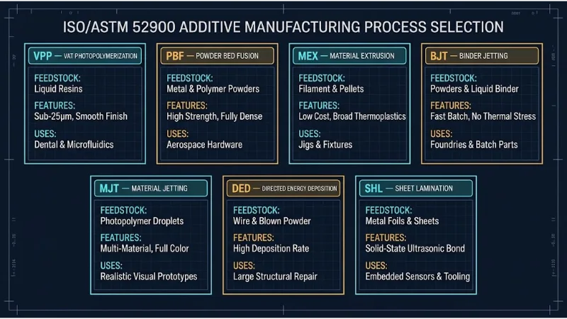
Figure 3: Systems engineering process selection logic. The path traces functional requirements from raw feedstock constraints through mechanical property and surface finish thresholds.
Worked Example: Cure Depth Calculation in Vat Photopolymerization
Problem: A stereolithography (VPP) system uses a 355 nm UV laser to cure an acrylic resin characterized by an optical penetration depth \(D_p = 0.15\text{ mm}\) and a critical exposure threshold \(E_c = 8.5\text{ mJ/cm}^2\). The scanning beam delivers a surface radiant exposure \(E_{max} = 32.0\text{ mJ/cm}^2\). Calculate the resulting cure depth \(C_d\) and determine whether this exposure provides adequate interlayer cross-linking for a programmed slice thickness of \(H = 0.10\text{ mm}\).
Step 1: Apply Jacobs' Working Curve Equation
$$ C_d = D_p \ln\left( \frac{E_{max}}{E_c} \right) = 0.15 \times \ln\left( \frac{32.0}{8.5} \right) $$ $$ \frac{E_{max}}{E_c} = \frac{32.0}{8.5} \approx 3.7647 $$ $$ C_d = 0.15 \times \ln(3.7647) = 0.15 \times 1.3256 \approx 0.1988\text{ mm} \approx 199\text{ \mu m} $$Step 2: Evaluate Interlayer Overcure Ratio
$$ \text{Overcure Margin} = C_d - H = 0.1988\text{ mm} - 0.10\text{ mm} = +0.0988\text{ mm} \approx 99\text{ \mu m} $$3. Interactive Energy-Matter Coupling Simulator
Select different AM processes and manipulate energy input parameters to observe real-time alterations in consolidation depth, thermal gradients, and layer fusion regimes.
4. Comparative Analysis: The 7 AM Processes
Each ISO/ASTM 52900 process category presents distinct operational trade-offs across volumetric build rate, feature resolution, residual stresses, and post-processing complexity:
| Process Category | Feedstock State | Consolidation Mechanism | Primary Technical Advantage | Critical Limitation |
|---|---|---|---|---|
| Vat Photopolymerization (VPP) | Liquid Photopolymer Resin | Photo-initiated radical/cationic polymerization | Highest feature resolution (<25 µm); superior optical surface finish. | Polymer aging/embrittlement; low thermal deflection resistance. |
| Powder Bed Fusion (PBF) | Powder (Metal, Polymer, Ceramic) | Thermal laser/electron-beam melting and sintering | Fully dense components; high mechanical integrity; self-supporting in polymers. | High residual stresses; slow build rates; hazardous powder handling. |
| Material Extrusion (MEX) | Solid Filament / Granules | Thermoplastic plastication and thermal reptation fusion | Lowest capital cost; broad engineering thermoplastic palette. | High mechanical anisotropy; pronounced staircase surface texture. |
| Binder Jetting (BJT) | Powder + Liquid Chemical Binder | Liquid capillary bridge necking (green state) + furnace sintering | Zero thermal residual stress during printing; fast batch throughput. | High isotropic shrinkage (15–22%) during sintering; residual porosity. |
| Material Jetting (MJT) | Liquid Droplets (Resin / Wax) | Photopolymer curing or thermal phase solidification | Multi-material and full-color gradation printing in a single layer. | High material cost; limited functional engineering mechanical properties. |
| Directed Energy Deposition (DED) | Powder Stream or Solid Wire | Laser, arc, or electron-beam melt pool consolidation | Extremely high deposition rate (>5 kg/hr); ideal for large part repair. | Poor geometric resolution; requires multi-axis finish machining. |
| Sheet Lamination (SHL) | Solid Sheets (Foil / Paper) | Adhesive bonding, thermal diffusion, or ultrasonic acoustic welding | Solid-state bonding (low temperature); allows dissimilar metal laminates. | High post-machining decubing effort; severe interlaminar shear weakness. |
5. ISO/ASTM 52900 Classification FAQ
Q1: Why does ISO/ASTM 52900 discourage terms like "3D Printing" or "Rapid Prototyping" in engineering documentation?
The standard deprecates colloquial terms because they fail to convey the underlying physics, machine architecture, or quality controls. "Rapid prototyping" historically implied non-functional aesthetic models, whereas modern AM produces mission-critical aerospace, automotive, and medical production hardware requiring precise process classification.
Q2: What is the fundamental physical distinction between Binder Jetting (BJT) and Material Jetting (MJT)?
In Binder Jetting (BJT), the printhead jets only a sacrificial chemical adhesive onto a dry powder bed, leaving the bulk material solid throughout printing. In Material Jetting (MJT), the printhead directly jets the actual build material droplets (photopolymer or wax), consolidating them on the fly via UV exposure or thermal freezing.
Q3: Why does Powder Bed Fusion produce higher residual stresses than Binder Jetting for the same metal alloy?
PBF relies on localized, high-energy laser melting followed by extreme cooling rates (\(10^4\text{ to }10^6\text{ K/s}\)), inducing severe thermal gradients and non-uniform thermal contraction. In contrast, BJT operates near room temperature during printing; consolidation occurs during a subsequent furnace sintering step where uniform heating eliminates thermal gradients.
Q4: What role does the dimensionless Ohnesorge number (Oh) play in Material Jetting?
The Ohnesorge number (\(Oh = \mu / \sqrt{\rho \gamma d}\)) relates viscous dissipation forces to surface tension and inertial forces. If \(Oh\) is too high, viscous damping prevents droplet ejection; if too low, surface tension cannot hold the droplet together, producing trailing satellite droplets that degrade print resolution.
Q5: How does Directed Energy Deposition (DED) achieve multi-material functional gradation?
Because DED delivers powder coaxially into the melt pool using separate pressurized hoppers, mass flow controllers can adjust the mixing ratio of different alloy powders dynamically during deposition. This allows continuous chemical composition gradients across a single build.
Q6: Why is Sheet Lamination (SHL) classified as a solid-state process in Ultrasonic Additive Manufacturing (UAM)?
In UAM, bonding occurs via acoustic scrubbing: high-frequency ultrasonic oscillations create high local shear strains that disrupt surface oxide layers, enabling direct metal-to-metal contact and atomic diffusion well below the melting temperature of the material.
6. ISO/ASTM 52900 Process Classification Self-Assessment
Tier 1: Foundational Practice (True/False & Concept Recall)
Q1.1: Which ISO/ASTM 52900 category includes Stereolithography (SLA) and Digital Light Processing (DLP)?
Q1.2: True or False: In Binder Jetting (BJT), full mechanical strength is achieved immediately upon completion of the printing cycle.
Q1.3: What physical parameter in Jacobs' equation dictates the rate of light attenuation in a photopolymer resin?
Q1.4: True or False: Wire Arc Additive Manufacturing (WAAM) is categorized under Powder Bed Fusion.
Q1.5: What primary force drives liquid infiltration between powder particles in Binder Jetting?
Q1.6: Why does polymer Powder Bed Fusion (e.g., SLS Nylon) typically not require sacrificial support structures?
Q1.7: What is the primary operational difference between DED and PBF?
Q1.8: Which AM process category permits the deposition of multi-material functional gradients and multi-color models within the same layer?
Tier 2: Applied Conceptual Cases & Process Debugging
Q2.1: Resolving delamination between layers in Stereolithography (VPP)
Analysis: The cure depth \(C_d\) was insufficient to provide adequate overcure into the preceding layer. According to Jacobs' curve \(C_d = D_p \ln(E_{max}/E_c)\), the engineer should either increase laser exposure time, decrease beam scan speed (to raise \(E_{max}\)), or reduce the programmed layer height \(H\) to ensure \(C_d > 1.3 \times H\).
Q2.2: Mitigating keyhole porosity in high-power Laser Powder Bed Fusion
Analysis: Excessive linear energy density (\(P/v\)) induced keyhole-mode melting, where metal vaporizes and forms a deep vapor cavity that collapses, trapping shielding gas bubbles. The engineer should reduce laser power \(P\) or increase scan velocity \(v\) to return to a stable conduction-mode melt pool.
Q2.3: Correcting non-uniform isotropic shrinkage in Binder Jet metal parts
Analysis: The difference arises from anisotropic powder packing: roller recoating creates higher packing density along the spreading plane than across the vertical build direction. The slicer's scaling factors must be adjusted asymmetrically (e.g., scaling Z by 1.282 and X/Y by 1.219) prior to printing.
Q2.4: Selection of process for refurbishing worn heavy-equipment driveshafts
Analysis: Powder Bed Fusion is impossible due to chamber size limits. Material Extrusion cannot deposit structural steel. Directed Energy Deposition (DED) mounted on a multi-axis robotic arm is the ideal ISO/ASTM 52900 process to deposit matching tool steel clad directly onto the worn geometry, followed by CNC finish turning.
Q2.5: Preventing satellite mist formation in Material Jetting printheads
Analysis: The fluid ink formulation's Ohnesorge number (\(Oh = \mu / \sqrt{\rho \gamma d}\)) has drifted outside the stable jetting window (\(0.1 < Oh < 1.0\)). This is typically caused by improper printhead temperature: if the printhead is too hot, fluid viscosity \(\mu\) drops excessively, causing the ejected filament to break into satellite droplets. Lowering nozzle temperature restores stable drop formation.
Q2.6: Choosing between SLS and FFF for an end-use intake manifold
Analysis: FFF (Material Extrusion) creates anisotropic weld lines that risk leaking under pressure and requires internal supports that cannot be removed from curved runners. Polymer PBF (SLS) is selected: it requires no internal supports and produces isotropic, pressure-tight Nylon parts suitable for end-use functional testing.
Q2.7: Bonding dissimilar metals without intermetallic embrittlement
Analysis: Ultrasonic Sheet Lamination (UAM) is the optimal solution. Because UAM is a solid-state consolidation process that operates well below bulk melting temperatures, it prevents the liquid-phase diffusion that forms brittle intermetallic compounds, producing sound metallurgical bonds between dissimilar metals.
Tier 3: Quantitative Numerical Engineering Problems
Q3.1: Calculating scan speed for target cure depth in SLA (VPP)
Steps: 1. Jacobs' curve inversion for required peak surface exposure \(E_{max}\): $$ C_d = D_p \ln\left( \frac{E_{max}}{E_c} \right) \implies \frac{E_{max}}{E_c} = \exp\left( \frac{C_d}{D_p} \right) $$ $$ \frac{E_{max}}{6.2} = \exp\left( \frac{0.18}{0.14} \right) = \exp(1.2857) \approx 3.6172 $$ $$ E_{max} = 6.2 \times 3.6172 = 22.427\text{ mJ/cm}^2 = 224.27\text{ J/m}^2 $$ 2. Peak radiant exposure of a Gaussian laser: $$ E_{max} = \sqrt{\frac{2}{\pi}} \frac{P_L}{w_0 v_s} $$ $$ v_s = \sqrt{\frac{2}{\pi}} \frac{P_L}{w_0 E_{max}} = 0.7979 \times \frac{0.120\text{ W}}{(0.00012\text{ m}) \times (224.27\text{ J/m}^2)} $$ $$ v_s = \frac{0.09575}{0.02691} \approx 3.558\text{ m/s} = 3558\text{ mm/s} $$
Q3.2: Computing volumetric energy density in Powder Bed Fusion
Steps: 1. Volumetric energy density formula: $$ E_v = \frac{P}{v \cdot h \cdot t} $$ 2. Substitute numerical parameters: $$ E_v = \frac{280\text{ W}}{(950\text{ mm/s}) \times (0.10\text{ mm}) \times (0.04\text{ mm})} = \frac{280}{3.80} \approx 73.68\text{ J/mm}^3 $$
Q3.3: Evaluating fluid droplet printability via the Ohnesorge number
Steps: 1. Calculate the inertial-capillary characteristic term: $$ \sqrt{\rho \gamma d} = \sqrt{1080 \times 0.035 \times (3.0 \times 10^{-5})} = \sqrt{1.134 \times 10^{-3}} \approx 0.03367\text{ Pa}\cdot\text{s} $$ 2. Compute \(Oh\): $$ Oh = \frac{\mu}{\sqrt{\rho \gamma d}} = \frac{0.018}{0.03367} \approx 0.5346 $$
Q3.4: Sintering volumetric shrinkage compensation in Binder Jetting
Steps: 1. Volumetric ratio and volumetric shrinkage \(S_V\): $$ \frac{V_{final}}{V_{green}} = \frac{\rho_{green}}{\rho_{final}} = \frac{0.56}{0.98} \approx 0.5714 $$ $$ S_V = 1 - 0.5714 = 0.4286 \quad (42.86\% \text{ volume loss}) $$ 2. Linear shrinkage ratio \(L_{final} / L_{green}\): $$ \frac{L_{final}}{L_{green}} = \left( \frac{V_{final}}{V_{green}} \right)^{1/3} = (0.5714)^{1/3} \approx 0.8299 $$ $$ S_L = 1 - 0.8299 = 0.1701 \quad (17.01\% \text{ linear shrinkage}) $$ 3. CAD compensation scale factor: $$ \text{Scale Factor} = \frac{L_{green}}{L_{final}} = \frac{1}{0.8299} \approx 1.2050 \quad (120.5\%) $$
Q3.5: Comparative deposition time: DED vs. Powder Bed Fusion
Steps: 1. Powder Bed Fusion build time: $$ t_{PBF} = \frac{1200\text{ cm}^3}{22\text{ cm}^3\text{/hr}} \approx 54.55\text{ hours} $$ 2. Directed Energy Deposition build + machining time: $$ t_{DED\_build} = \frac{1200\text{ cm}^3}{1800\text{ cm}^3\text{/hr}} = 0.67\text{ hours} \approx 40\text{ minutes} $$ $$ t_{total\_DED} = 0.67\text{ hr} + 3.50\text{ hr} = 4.17\text{ hours} $$
Q3.6: Capillary wetting pressure in fine vs. coarse Binder Jetting powders
Steps: 1. Capillary pressure equation: $$ P_c = \frac{2\gamma \cos(\theta)}{r} $$ $$ 2\gamma \cos(\theta) = 2 \times 0.048 \times \cos(22^\circ) = 0.096 \times 0.92718 \approx 0.08901\text{ N/m} $$ 2. Capillary pressure for Powder A (\(r_A = 4\text{ \mu m}\)): $$ P_{c,A} = \frac{0.08901}{4.0 \times 10^{-6}} \approx 22252.5\text{ Pa} \approx 22.25\text{ kPa} $$ 3. Capillary pressure for Powder B (\(r_B = 18\text{ \mu m}\)): $$ P_{c,B} = \frac{0.08901}{1.8 \times 10^{-5}} \approx 4945.0\text{ Pa} \approx 4.95\text{ kPa} $$
Interactive Education Hub Navigation
Continue exploring the Additive Manufacturing series across related computational and hardware modules:
Slicing Mathematics & Toolpaths
Learn the vector math of STL facet-plane intersections and Ray-Casting parity rules that feed toolpaths into AM engines.
Overhang Limits & Support Physics
Explore layer overlap limits, powder bed thermal heat sinking, and support scaffold structural mechanics.
The ISO/ASTM 52900 7 Categories
Consolidation thermodynamics, feedstock states, and energy-matter interactions across the seven standardized AM families.