
Heat exchangers are devices that transfer thermal energy from one fluid to another, usually without allowing the fluids to mix. They are found in engines, power plants, air-conditioning systems, refrigerators, chemical plants, data centres, electric vehicles, food processing equipment, and many renewable energy systems.
This page belongs to the Heat Transfer cluster within Thermodynamics. It builds on Heat Conduction, Heat Convection, and Thermal Resistance. It also connects naturally with Thermal Radiation and prepares students for Combined Heat Transfer.
The central idea is simple: one fluid is hotter than another, and heat flows from the hotter fluid to the colder fluid through a separating surface. The heat exchanger is designed to make this transfer effective, controlled, safe, and economical.
A heat exchanger is not merely a pipe or a container. It is a carefully designed thermal pathway. It must provide enough surface area for heat transfer, enough fluid motion for convection, enough material conductivity for conduction through walls, and enough pressure control so the fluids can move without excessive pumping power.
What Heat Exchangers Really Are
A heat exchanger is a device that allows heat to move from a hot fluid to a cold fluid. In many designs, the two fluids are separated by a solid wall. Heat first transfers from the hot fluid to the wall by convection, then conducts through the wall, and finally transfers from the wall to the cold fluid by convection.
This means that a heat exchanger usually combines several heat-transfer processes:
| Heat-Transfer Step | Physical Process | Where It Happens |
|---|---|---|
| Hot fluid to wall | Convection | On the hot-fluid side |
| Through the separating wall | Conduction | Across the tube, plate, or surface material |
| Wall to cold fluid | Convection | On the cold-fluid side |
| Surface radiation | Radiation, when significant | High-temperature or exposed surfaces |
This is why heat exchangers are an excellent bridge between the separate topics of conduction, convection, and thermal resistance. They show students how heat-transfer theory becomes real engineering design.
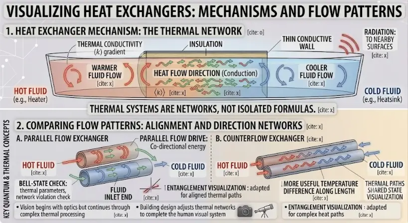
Visualizing heat exchangers. The top panel illustrates the microscopic mechanisms and macroscopic flows of a thermal network, comparing hot and cold fluid streams separated by a thin conductive wall. The lower panels compare flow patterns, demonstrating the co-directional parallel flow and the cross-directional counterflow, highlighting the more effective energy transfer and useful temperature difference in the counterflow exchanger.
The image is a comprehensive multi-panel scientific educational infographic illustration titled “VISUALIZING HEAT EXCHANGERS: MECHANISMS AND FLOW PATTERNS,” set against a clean white background with subtle geometric and network traces. It adopts a diagrammatic style with soft glowing accents and clear textual labels, linked by a large central horizontal title banner adapted from image_47.png, highlighting the core concept: “THERMAL SYSTEMS ARE NETWORKS, NOT ISOLATED FORMULAS”.
Part 1: Heat Exchanger Mechanism: The Thermal Network
This upper panel provides a visual model of heat transfer mechanisms and macroscopic flows:- Cross-Section and Fluid Streams: A detailed cross-section of a heat exchanger section is depicted, inspired by the container in Section 1 of image_47.png. A prominent “THIN CONDUCTIVE WALL” divides the interior. On one side, a labeled “HOT FLUID” stream flows with swirling red and orange arrows, labeled “WARMER FLUID FLOW”. On the other side, a labeled “COLD FLUID” stream flows with blue swirling arrows, labeled “COOLER FLUID FLOW”.
- Flow Tracking and Microscopic Mechanism: Countless small, multi-directional green and red wave arrows cross the thin conductive wall, demonstrating “HEAT FLOW DIRECTION (Conduction)” with a direct link between macroscopic flow and microscopic behavior. Callouts detail: “THERMAL CONDUCTIVITY (k) gradient”, “INSULATION” around the container top, and “RADIATION: TO NEARBY SURFACES”, adapted to the context. Quantum kets like |k⟩ and citation brackets are integrated into the diagrammatic flow, suggesting a connection between the macroscopic fluid flow and microscopic concepts.
Part 2: Comparing Flow Patterns: Alignment and Direction Networks
This lower panel illustrates the difference in flow patterns using two distinct sub-diagrams, Arranged in stacked formations adapted from Section 2 of image_47.png:- Sub-Diagram A: Parallel Flow Exchanger: On the left, this section shows a magnified view of two parallel fluid streams in pipes, similar to the microscopic matrix layout of image_47.png. Both “HOT FLUID” (red arrows) and “COLD FLUID” (blue arrows) enter from the same “FLUID INLET END”. Small green flow arrows trace their co-directional path. Callouts repeat quantum concepts, including “PARALLEL FLOW DRIVE: Co-directional energy”, “BELL-STATE CHECK: thermal parameters, network violation check”, and adapted entanglement and shared state visualization concepts.
- Sub-Diagram B: Counterflow Exchanger: On the right, this section shows two parallel streams moving in opposite directions, with “HOT FLUID” entering from the left and “COLD FLUID” entering from the right. A prominent label states: “MORE USEFUL TEMPERATURE DIFFERENCE ALONG LENGTH”, emphasizing the more efficient energy transfer. Blue and red wave arrows show the useful energy transfer. Callouts repeat quantum concepts and summaries.
- Summaries and Context: Bullet points at the bottom reiterate summaries from image_47.png: “Vision begins with optics but continues through complex thermal processing” and “Building design adjusts thermal networks to complete the human visual system”. Small icons of a camera and a telescope are present.
Why Heat Exchangers Are Used
Heat exchangers are used because many systems need to move heat without mixing fluids. Engine coolant should not mix with air. Refrigerant should not mix with room air. Steam in a power plant condenser should not mix with cooling water. Food-processing fluids may need controlled heating without contamination.
Heat exchangers allow engineers to control heat transfer while keeping fluids separated, contained, reusable, or safe.
| Need | Heat Exchanger Role | Example |
|---|---|---|
| Cool a hot system | Carry heat away to another fluid | Car radiator cooling engine coolant |
| Heat a cold stream | Transfer heat from a hot stream | Water heater or industrial preheater |
| Recover waste heat | Use outgoing heat to warm incoming fluid | Heat recovery ventilator |
| Condense vapour | Remove latent heat from vapour | Power plant condenser |
| Evaporate liquid | Add heat to change liquid into vapour | Refrigerator evaporator |
| Protect safety and purity | Separate fluids while transferring heat | Food, medical, and chemical processing |
Basic Energy Balance
A heat exchanger must obey energy conservation. If heat losses to the surroundings are small, the heat lost by the hot fluid is approximately equal to the heat gained by the cold fluid.
Q̇hot ≈ Q̇cold
For a fluid with no phase change, the heat-transfer rate can often be estimated using:
Q̇ = ṁcp(Tout – Tin)
Here, ṁ is mass flow rate, cp is specific heat capacity, and Tout – Tin is the temperature change of the fluid.
| Symbol | Meaning | Common Unit |
|---|---|---|
| Q̇ | Heat-transfer rate | W |
| ṁ | Mass flow rate | kg/s |
| cp | Specific heat capacity at constant pressure | J/(kg·K) |
| Tin | Inlet temperature | °C or K |
| Tout | Outlet temperature | °C or K |
This energy balance is usually the first step in heat-exchanger analysis. It tells us how much heat must be transferred before we worry about surface area, geometry, or flow arrangement.
Overall Heat-Transfer Coefficient
In a heat exchanger, heat must pass through several resistances. The hot-fluid side has convection resistance. The wall has conduction resistance. The cold-fluid side has convection resistance. Deposits, fouling, or surface films may add extra resistance.
To simplify this, engineers often use an overall heat-transfer coefficient U. A common heat-exchanger equation is:
Q̇ = UAΔTeffective
Here, U represents the combined effect of all thermal resistances, A is heat-transfer area, and ΔTeffective is the effective temperature difference between the fluids.
| Factor | Effect on Heat Exchanger Performance |
|---|---|
| Larger U | Stronger heat transfer for the same area and temperature difference |
| Larger A | More surface available for heat transfer |
| Larger effective temperature difference | Greater driving force for heat transfer |
| Higher fouling resistance | Lower overall heat-transfer performance |
Thermal Resistance View of a Heat Exchanger
The overall coefficient U can be understood using thermal resistance. For a simple flat wall separating two fluids:
1 ⁄ UA = 1 ⁄ hhA + L ⁄ kA + 1 ⁄ hcA
Here, hh is the hot-side convection coefficient, hc is the cold-side convection coefficient, L is wall thickness, and k is wall thermal conductivity.
| Resistance Term | Meaning | Design Response |
|---|---|---|
| 1 ⁄ hhA | Hot-side convection resistance | Improve flow, turbulence, or surface design |
| L ⁄ kA | Wall conduction resistance | Use thinner or more conductive wall material |
| 1 ⁄ hcA | Cold-side convection resistance | Improve flow distribution or use enhanced surfaces |
| Fouling resistance | Resistance from deposits or scaling | Clean surfaces, treat fluids, or allow fouling margin |
The largest resistance often controls the performance. A highly conductive wall cannot compensate for very poor convection on one side, and strong convection cannot fully overcome a badly fouled surface.
Flow Arrangements in Heat Exchangers
The way fluids move through a heat exchanger strongly affects performance. The three common arrangements are parallel flow, counterflow, and crossflow.
| Flow Arrangement | Description | Typical Feature |
|---|---|---|
| Parallel flow | Both fluids enter from the same end and move in the same direction | Simple, but temperature difference decreases quickly |
| Counterflow | Fluids move in opposite directions | Often more thermally effective |
| Crossflow | One fluid flows across the direction of the other | Common in radiators, air coolers, and compact exchangers |
Counterflow heat exchangers are often preferred when high thermal performance is needed because they can maintain a more useful temperature difference along the exchanger length.
Parallel-Flow Heat Exchangers
In a parallel-flow heat exchanger, the hot and cold fluids enter from the same end and travel in the same direction. The temperature difference is largest near the inlet, but it becomes smaller as both fluids move along the exchanger.
Parallel flow is simple and sometimes useful, but it may not achieve as much heat transfer as counterflow for the same size and conditions.
| Parallel-Flow Feature | Effect |
|---|---|
| Both fluids enter together | Large initial temperature difference |
| Temperatures approach each other along the length | Temperature driving force weakens |
| Cold outlet cannot usually exceed hot outlet temperature | Limits heating performance |
| Simple arrangement | May be easier to build in some systems |
Counterflow Heat Exchangers
In a counterflow heat exchanger, the hot and cold fluids move in opposite directions. This arrangement often gives better performance because the temperature difference can remain more evenly distributed along the exchanger.
In a well-designed counterflow exchanger, the cold fluid may leave at a temperature higher than the hot-fluid outlet temperature, although it cannot exceed the hot-fluid inlet temperature.
| Counterflow Feature | Effect |
|---|---|
| Fluids move in opposite directions | Temperature difference remains useful along the length |
| Often higher effectiveness | More heat transfer for a given area |
| Can heat cold stream strongly | Useful for heat recovery and preheating |
| Design may be more complex | Requires careful flow arrangement and sealing |
Crossflow Heat Exchangers
In a crossflow heat exchanger, one fluid flows across the direction of the other. This arrangement is common when one of the fluids is air.
Car radiators, air-conditioning coils, air-cooled condensers, and many compact heat exchangers use crossflow because air can pass across tubes or fins while another fluid flows inside.
| Crossflow Example | Fluid Arrangement |
|---|---|
| Car radiator | Coolant flows inside tubes while air passes across fins |
| Air-conditioner coil | Refrigerant flows inside tubes while air flows across the coil |
| Air-cooled heat sink | Air flows across fins attached to a hot base |
| Industrial air heater | Air passes across tubes carrying hot fluid or steam |
Log Mean Temperature Difference
In a heat exchanger, the temperature difference between the hot and cold fluids usually changes along the length. The log mean temperature difference, or LMTD, gives an effective average temperature difference for heat-transfer calculation.
ΔTlm = (ΔT1 – ΔT2) ⁄ ln(ΔT1 / ΔT2)
Then the heat-transfer rate can be estimated by:
Q̇ = UAΔTlm
| Quantity | Meaning |
|---|---|
| ΔT1 | Temperature difference between the two fluids at one end |
| ΔT2 | Temperature difference between the two fluids at the other end |
| ΔTlm | Effective average temperature difference |
| U | Overall heat-transfer coefficient |
| A | Heat-transfer area |
The LMTD method is especially useful when inlet and outlet temperatures are known or can be estimated.
Effectiveness-NTU Method
Another common heat-exchanger method is the effectiveness-NTU method. It is useful when outlet temperatures are not known at the start.
Heat exchanger effectiveness is defined as:
ϵ = Q̇actual ⁄ Q̇max
The maximum possible heat transfer is based on the smaller heat-capacity rate:
Cmin = min(ṁhcp,h, ṁccp,c)
The number of transfer units is:
NTU = UA ⁄ Cmin
| Quantity | Meaning |
|---|---|
| ϵ | Effectiveness of the heat exchanger |
| Q̇actual | Actual heat-transfer rate |
| Q̇max | Maximum possible heat-transfer rate |
| Cmin | Smaller heat-capacity rate of the two fluids |
| NTU | Number of transfer units |
The effectiveness-NTU method is widely used in design studies because it links exchanger size, flow arrangement, and heat-transfer performance.
Common Types of Heat Exchangers
Heat exchangers come in many forms because different applications require different pressures, temperatures, fluids, cleanliness, compactness, and maintenance access.
Double-Pipe Heat Exchanger
One fluid flows through an inner pipe while another flows through the surrounding annular space. It is simple and useful for small duties.Shell-and-Tube Heat Exchanger
One fluid flows through many tubes while another flows around them inside a shell. It is widely used in power plants, refineries, and chemical processing.Plate Heat Exchanger
Thin plates create alternating channels for hot and cold fluids. This design provides large area in a compact space.Finned-Tube Heat Exchanger
Fins increase surface area on the air side, making it useful for radiators, air-conditioners, and air-cooled systems.Compact Heat Exchanger
Small passages and high surface-area density allow strong heat transfer in limited space.Regenerative Heat Exchanger
A solid matrix stores heat from one fluid and later transfers it to another, often used in heat recovery systems.Shell-and-Tube Heat Exchangers
Shell-and-tube heat exchangers are among the most common industrial heat exchangers. They contain many tubes inside a larger shell. One fluid flows inside the tubes, while the other flows around the outside of the tubes inside the shell.
| Feature | Purpose |
|---|---|
| Many tubes | Provide large heat-transfer area |
| Shell side | Allows another fluid to flow around the tubes |
| Baffles | Guide shell-side flow and increase mixing |
| Tube sheets | Hold tubes in place and separate fluids |
| Removable bundles | Allow inspection and cleaning in some designs |
Shell-and-tube designs are valued because they can handle high pressures, large duties, phase change, and industrial fluids. Their design, however, can be complex.
Plate Heat Exchangers
Plate heat exchangers use thin metal plates to create alternating channels for hot and cold fluids. The plates often have corrugated patterns to increase turbulence and strengthen heat transfer.
| Advantage | Explanation |
|---|---|
| Compact size | Large surface area fits into a small volume |
| High heat-transfer coefficient | Corrugated channels promote mixing and thin boundary layers |
| Easy expansion in some designs | More plates can be added to increase capacity |
| Useful for liquid-liquid exchange | Common in HVAC, food processing, and heat recovery |
Plate heat exchangers may not be suitable for every high-pressure or dirty-fluid application, but they are excellent where compactness and strong heat transfer are important.
Finned Heat Exchangers
Fins are used when one side of a heat exchanger has weak convection. This often happens on the air side because air has relatively low density, thermal conductivity, and heat capacity compared with liquids.
Adding fins increases the surface area exposed to air, allowing more heat to be transferred.
| Finned Exchanger Example | Purpose |
|---|---|
| Car radiator | Increase air-side heat-transfer area |
| Air-conditioner evaporator coil | Transfer heat from room air to refrigerant |
| Electronics heat sink | Spread heat into fins so air can remove it |
| Air-cooled condenser | Reject heat from refrigerant to outdoor air |
Fins must conduct heat well enough along their length. A fin with poor conduction may add area but not use that area effectively.
Heat Exchangers with Phase Change
Many important heat exchangers involve phase change. During condensation or boiling, large amounts of energy can be transferred at nearly constant temperature.
| Phase-Change Device | Process | Example |
|---|---|---|
| Condenser | Vapour releases heat and becomes liquid | Power plant condenser, air-conditioner outdoor coil |
| Evaporator | Liquid absorbs heat and becomes vapour | Refrigerator evaporator, air-conditioner indoor coil |
| Boiler | Liquid is heated to produce vapour | Steam generator in a power plant |
| Heat pipe | Evaporation and condensation move heat internally | Electronics cooling and spacecraft thermal control |
Phase-change heat exchangers can be very effective, but they require careful control of pressure, temperature, flow distribution, and safety conditions.
Fouling in Heat Exchangers
Fouling occurs when unwanted material builds up on heat-transfer surfaces. This may include scale, corrosion products, biological growth, dirt, oil deposits, soot, or chemical residues.
Fouling adds thermal resistance and often increases pressure drop. Over time, it can reduce heat-transfer performance and raise energy costs.
| Fouling Type | Example | Effect |
|---|---|---|
| Scaling | Mineral deposits from hard water | Reduces heat transfer and narrows flow passages |
| Biological fouling | Microorganisms in cooling water | Creates deposits and flow restrictions |
| Particulate fouling | Dirt, dust, or suspended solids | Blocks passages or coats surfaces |
| Corrosion fouling | Oxide layers or corrosion products | Adds resistance and may damage equipment |
| Combustion fouling | Soot on heating surfaces | Reduces boiler or furnace efficiency |
Good design includes fouling allowance, cleaning access, suitable materials, proper water treatment, filtration, and regular maintenance.
Pressure Drop and Pumping Power
A heat exchanger must transfer heat, but it must also allow fluids to flow. If passages are too narrow or flow is too turbulent, pressure drop increases. Pumps or fans must then use more energy to move the fluids.
| Design Choice | Heat-Transfer Benefit | Possible Cost |
|---|---|---|
| Narrower channels | Better heat transfer and compactness | Higher pressure drop |
| Higher flow speed | Stronger convection | More pumping power |
| More fins or surface enhancement | Larger surface area | More flow resistance and fouling risk |
| More passes | Better temperature control | More complex flow path |
Good heat-exchanger design is therefore a balance between heat-transfer performance and fluid-flow cost.
Materials Used in Heat Exchangers
Heat-exchanger materials must conduct heat, resist corrosion, withstand pressure, tolerate temperature, and remain compatible with the fluids.
| Material | Why It Is Used | Typical Application |
|---|---|---|
| Copper and copper alloys | High thermal conductivity and good workability | HVAC coils, water systems, compact exchangers |
| Aluminium | Lightweight and good thermal conductivity | Radiators, air coolers, automotive systems |
| Stainless steel | Corrosion resistance and strength | Food, chemical, marine, and sanitary systems |
| Titanium | Strong corrosion resistance in seawater | Marine and desalination systems |
| Nickel alloys | High-temperature and corrosion resistance | Chemical and high-temperature applications |
| Polymers and composites | Corrosion resistance and low weight | Special low-temperature or corrosive-fluid systems |
The best material is not always the one with the highest thermal conductivity. Cost, corrosion, pressure, manufacturability, cleanliness, and lifetime must also be considered.
Everyday Examples of Heat Exchangers
Car Radiator
Hot engine coolant flows through tubes while air passes across fins, transferring engine heat to the surroundings.Air Conditioner
Evaporator and condenser coils transfer heat between indoor air, refrigerant, and outdoor air.Refrigerator
The evaporator absorbs heat from inside the refrigerator, while the condenser rejects heat to the room.Water Heater
Heat is transferred from combustion gases, electricity, or another hot fluid into water.Laptop Cooling System
Heat pipes, fins, and fans transfer heat from chips to surrounding air.Heat Recovery Ventilator
Outgoing warm air preheats incoming fresh air without mixing the two air streams.Applications of Heat Exchangers
Heat exchangers appear in almost every industry because heat must often be recovered, removed, added, or controlled.
Power Plants
Boilers, condensers, feedwater heaters, and cooling systems all depend on heat exchangers.HVAC Systems
Coils, chillers, heat pumps, and ventilation systems use heat exchangers to control indoor comfort.Refrigeration
Evaporators and condensers move heat from cold spaces to warmer surroundings.Chemical Processing
Reactors, distillation columns, condensers, reboilers, and process heaters require controlled heat transfer.Food and Beverage Processing
Pasteurisation, sterilisation, cooling, and temperature control depend on hygienic heat exchangers.Electric Vehicles
Battery packs, motors, inverters, and charging systems need compact heat exchangers for thermal management.Data Centres
Liquid cooling loops and air-handling systems remove heat from servers and power electronics.Renewable Energy Systems
Solar thermal systems, geothermal plants, heat pumps, and waste-heat recovery systems rely on heat exchangers.Challenges and Practical Limitations
Heat exchangers look simple in diagrams, but real design involves many trade-offs. Improving one aspect of performance may make another aspect worse.
| Challenge | Why It Matters | Example |
|---|---|---|
| Fouling | Adds resistance and lowers heat-transfer performance | Scale inside tubes |
| Pressure drop | Requires more pump or fan power | Compact channels with high flow speed |
| Flow maldistribution | Some regions may transfer little heat | Uneven flow in plate or shell-side passages |
| Thermal stress | Temperature differences cause expansion and mechanical stress | Hot tube bundles during startup |
| Corrosion | Can reduce lifetime and contaminate fluids | Seawater or chemical processing systems |
| Leakage risk | Fluids may contaminate each other | Food processing or toxic chemical systems |
| Phase-change instability | Boiling and condensation can be uneven or difficult to control | Evaporators and condensers |
| Maintenance access | Cleaning and inspection may be difficult | Compact exchangers with narrow passages |
The practical lesson is that heat-exchanger design is not only a heat-transfer problem. It is also a fluid mechanics, materials, maintenance, safety, cost, and reliability problem.
Future Directions and Emerging Trends
Heat exchangers are evolving because modern systems demand higher efficiency, smaller size, better reliability, and lower environmental impact.
Compact Heat Exchangers
Smaller channels and denser surface areas allow high heat transfer in limited space.Microchannel Cooling
Microchannels are used in electronics, batteries, and high-heat-flux systems where compact cooling is needed.Additive Manufacturing
3D printing can create complex internal passages that are difficult to make using traditional manufacturing.Advanced Surface Coatings
Coatings can reduce fouling, improve boiling or condensation, and protect against corrosion.Low-Carbon Heating and Cooling
Heat pumps, heat recovery, and district energy systems require efficient heat exchangers.Battery and EV Thermal Systems
Electric vehicles require lightweight, compact, and reliable heat exchangers for cells and power electronics.Data Centre Liquid Cooling
Liquid-to-liquid and liquid-to-air heat exchangers are increasingly important for high-density computing.AI-Assisted Thermal Design
Simulation and optimisation tools can help balance heat transfer, pressure drop, fouling, and cost.Connections with Wider Physics and Technology
Heat exchangers connect heat-transfer theory with practical energy systems, engineering design, buildings, vehicles, electronics, and industrial processes.
Thermodynamics
Heat exchangers apply thermodynamic energy balances to real systems where fluids exchange thermal energy.Heat Transfer
Heat exchangers bring together conduction, convection, thermal resistance, and sometimes radiation.Heat Conduction
Heat must conduct through tube walls, plates, fins, coatings, and thermal interfaces.Heat Convection
Fluid motion on both sides of the exchanger controls much of the heat-transfer performance.Thermal Resistance
Overall heat-transfer coefficients are built from convection, conduction, fouling, and contact resistances.Engineering Thermodynamics
Power cycles, refrigeration cycles, engines, and industrial energy systems rely on heat exchangers.Learning Pathway Within Heat Transfer
Heat Exchangers is the fifth step in the Heat Transfer pathway. After learning the basic heat-transfer mechanisms and resistance models, students now see how these ideas are combined in practical equipment.
Heat Conduction
Learn how heat moves through materials by molecular interactions, electron motion, and temperature gradients.Heat Convection
Study how fluids transfer heat through natural motion, forced flow, boundary layers, and mixing.Thermal Radiation
Explore how heat travels by electromagnetic waves, even through empty space.Thermal Resistance
Learn how resistance models help analyse heat flow through layers, walls, insulation, interfaces, and cooling paths.Heat Exchangers
Current page. See how devices transfer heat between fluids in engines, power plants, HVAC systems, refrigeration, and industry.Combined Heat Transfer
Understand how conduction, convection, and radiation work together in real thermal systems.Quick Check: Heat Exchangers
Quick Check: Heat Exchanger Basics
Q1. What is the main purpose of a heat exchanger?
A heat exchanger transfers heat from one fluid to another, usually while keeping the fluids separated.
Q2. Why is counterflow often more effective than parallel flow?
Counterflow can maintain a useful temperature difference along more of the exchanger length, allowing more heat transfer for a given area.
Q3. What does the overall heat-transfer coefficient U represent?
The coefficient U represents the combined effect of convection, conduction, fouling, and other resistances between the two fluids.
Q4. Why is fouling a problem in heat exchangers?
Fouling adds thermal resistance and may also increase pressure drop, reducing performance and increasing energy cost.
Common Misunderstandings About Heat Exchangers
Misunderstanding 1: The Fluids Must Mix to Exchange Heat
Many heat exchangers keep the fluids separated by a wall. Heat transfers through the wall without mixing the fluids.
Misunderstanding 2: Bigger Is Always Better
More area can improve heat transfer, but it may also increase size, cost, pressure drop, material use, and maintenance difficulty.
Misunderstanding 3: Heat Exchangers Are Only Used for Cooling
Heat exchangers can cool, heat, condense, evaporate, recover waste heat, or maintain controlled temperatures.
Misunderstanding 4: High Flow Rate Is Always Best
Higher flow rate can improve convection, but it also increases pressure drop and pumping power. The best design balances heat transfer and energy use.
Misunderstanding 5: The Wall Material Is the Only Important Factor
Wall conductivity matters, but convection coefficients, fouling, flow arrangement, area, pressure drop, and fluid properties may be equally or more important.
Key Terms
- Heat exchanger
- A device that transfers heat between fluids, usually while keeping the fluids separated.
- Hot fluid
- The fluid that loses thermal energy in the heat exchanger.
- Cold fluid
- The fluid that gains thermal energy in the heat exchanger.
- Overall heat-transfer coefficient
- A coefficient U representing the combined effect of several heat-transfer resistances.
- Parallel flow
- A flow arrangement in which hot and cold fluids move in the same direction.
- Counterflow
- A flow arrangement in which hot and cold fluids move in opposite directions.
- Crossflow
- A flow arrangement in which one fluid moves across the direction of the other.
- LMTD
- Log mean temperature difference, an effective average temperature difference used in heat-exchanger calculations.
- Effectiveness
- The ratio of actual heat transfer to the maximum possible heat transfer.
- NTU
- Number of transfer units, a measure of heat-exchanger size relative to heat-capacity rate.
- Fouling
- Unwanted deposit buildup on heat-transfer surfaces that increases resistance and reduces performance.
- Pressure drop
- The pressure loss that occurs as fluid flows through passages, tubes, channels, or fittings.
Frequently Asked Questions: Heat Exchangers
What is a heat exchanger?
A heat exchanger is a device that transfers heat from one fluid to another, usually without allowing the fluids to mix.
Where are heat exchangers used?
Heat exchangers are used in engines, radiators, air-conditioners, refrigerators, power plants, chemical plants, food processing, data centres, and electric vehicles.
How does a heat exchanger transfer heat?
Heat usually moves by convection from the hot fluid to a wall, conduction through the wall, and convection from the wall to the cold fluid.
What is the difference between parallel flow and counterflow?
In parallel flow, both fluids move in the same direction. In counterflow, the fluids move in opposite directions, often improving heat-transfer performance.
What is crossflow?
Crossflow occurs when one fluid flows across the direction of the other. It is common in radiators, air-conditioning coils, and air-cooled heat exchangers.
What is the overall heat-transfer coefficient?
The overall heat-transfer coefficient U represents the combined effect of convection, conduction, fouling, and other thermal resistances.
What is LMTD?
LMTD stands for log mean temperature difference. It gives an effective average temperature difference for heat-transfer calculations.
What is heat exchanger effectiveness?
Effectiveness is the ratio of actual heat transfer to the maximum possible heat transfer for the given fluid inlet conditions.
Why is fouling important?
Fouling adds thermal resistance and can reduce heat-transfer rate, increase pressure drop, and raise operating cost.
Why do heat exchangers use fins?
Fins increase surface area, especially on the air side where convection is often weak.
Why is pressure drop important?
Pressure drop determines how much pump or fan power is needed to move fluids through the heat exchanger.
Why should students learn heat exchangers?
Heat exchangers show how conduction, convection, thermal resistance, energy balance, and fluid flow combine in real engineering systems.
Review Questions and Answers
- What is the main function of a heat exchanger?Answer: Its main function is to transfer heat from one fluid to another, usually without mixing the fluids.
- What heat-transfer modes usually occur in a heat exchanger?Answer: Heat usually transfers by convection from the hot fluid to the wall, conduction through the wall, and convection from the wall to the cold fluid.
- What is the basic energy balance for a well-insulated heat exchanger?Answer: The heat lost by the hot fluid is approximately equal to the heat gained by the cold fluid.
- What does the overall heat-transfer coefficient U represent?Answer: It represents the combined effect of all heat-transfer resistances between the two fluids.
- Why is counterflow often more effective than parallel flow?Answer: Counterflow maintains a more useful temperature difference along the exchanger length, allowing more heat transfer.
- What is fouling?Answer: Fouling is unwanted deposit buildup on heat-transfer surfaces, increasing resistance and reducing performance.
- Why do many heat exchangers use fins?Answer: Fins increase surface area, which improves heat transfer, especially when one fluid is air.
- Why must pressure drop be considered?Answer: Higher pressure drop requires more pump or fan power, increasing operating cost.
Thought-Provoking Questions and Answers
- Why is a heat exchanger a good example of combined heat transfer?Answer: It usually involves convection on both fluid sides, conduction through a wall, and sometimes radiation or fouling resistance. These effects work together rather than separately.
- Why is the best heat exchanger not always the one with the highest heat-transfer rate?Answer: The best design must balance heat transfer with pressure drop, cost, size, safety, fouling, maintenance, and material limits.
- Why does waste heat recovery matter for sustainability?Answer: Waste heat recovery uses energy that would otherwise be rejected, improving overall efficiency and reducing fuel or electricity demand.
- Why can a small amount of fouling cause a large performance problem?Answer: Fouling may add a high-resistance layer exactly where heat must cross between fluid and wall, reducing the overall heat-transfer coefficient.
- Why are heat exchangers important in electric vehicles?Answer: Batteries, motors, chargers, and power electronics all generate heat. Compact heat exchangers help keep these components within safe operating temperatures.
- What does heat-exchanger design teach about engineering trade-offs?Answer: It shows that improving performance in one area can create costs elsewhere. Better heat transfer may require more area, higher flow speed, more materials, or more pumping power.
Numerical Problems and Solutions
- Water flows through a heat exchanger at ṁ = 0.50 kg/s. Its temperature rises from 20 °C to 50 °C. Using cp = 4180 J/(kg·K), find the heat-transfer rate.Solution:
- Use Q̇ = ṁcp(Tout – Tin).
- ΔT = 50 – 20 = 30 K.
- Q̇ = (0.50)(4180)(30).
- Q̇ = 62700 W.
Answer: The heat-transfer rate is 62.7 kW. - A heat exchanger has U = 250 W/(m2·K), area A = 12 m2, and ΔTlm = 40 K. Find Q̇.Solution:
- Use Q̇ = UAΔTlm.
- Q̇ = (250)(12)(40).
- Q̇ = 120000 W.
Answer: The heat-transfer rate is 120 kW. - For a heat exchanger, ΔT1 = 60 K and ΔT2 = 30 K. Find the log mean temperature difference.Solution:
- Use ΔTlm = (ΔT1 – ΔT2) ⁄ ln(ΔT1 / ΔT2).
- ΔTlm = (60 – 30) ⁄ ln(60 / 30).
- ΔTlm = 30 ⁄ ln 2.
- ln 2 ≈ 0.693.
- ΔTlm ≈ 43.3 K.
Answer: The log mean temperature difference is approximately 43.3 K. - A heat exchanger must transfer 80 kW. If U = 400 W/(m2·K) and ΔTlm = 25 K, find the required area.Solution:
- Use Q̇ = UAΔTlm.
- Rearrange: A = Q̇ ⁄ UΔTlm.
- Convert 80 kW = 80000 W.
- A = 80000 ⁄ (400)(25).
- A = 80000 ⁄ 10000 = 8.0 m2.
Answer: The required heat-transfer area is 8.0 m2. - The hot fluid in a heat exchanger loses 150 kW. If heat loss to the surroundings is negligible, how much heat does the cold fluid gain?Solution:
- For a well-insulated heat exchanger, heat lost by the hot fluid is approximately heat gained by the cold fluid.
- Q̇cold ≈ 150 kW.
Answer: The cold fluid gains approximately 150 kW. - A heat exchanger has UA = 5000 W/K and Cmin = 2000 W/K. Find the number of transfer units.Solution:
- Use NTU = UA ⁄ Cmin.
- NTU = 5000 ⁄ 2000.
- NTU = 2.5.
Answer: The number of transfer units is 2.5. - A heat exchanger transfers 60 kW, while the maximum possible heat transfer is 100 kW. Find its effectiveness.Solution:
- Use ϵ = Q̇actual ⁄ Q̇max.
- ϵ = 60 ⁄ 100.
- ϵ = 0.60.
Answer: The heat exchanger effectiveness is 0.60, or 60%. - A heat exchanger originally has U = 600 W/(m2·K). Fouling reduces it to 450 W/(m2·K). If area and temperature difference remain the same, by what percentage does the heat-transfer rate decrease?Solution:
- Since Q̇ = UAΔT, heat-transfer rate is proportional to U when A and ΔT are constant.
- Fraction remaining = 450 ⁄ 600 = 0.75.
- Decrease = 1 – 0.75 = 0.25.
- Percentage decrease = 25%.
Answer: The heat-transfer rate decreases by 25%.
External References for Further Reading
The following references provide useful background on heat exchangers, overall heat-transfer coefficients, heat-transfer mechanisms, and practical design ideas.
- OpenStax University Physics: Mechanisms of Heat Transfer — A clear overview of conduction, convection, and radiation.
- Engineering ToolBox: Heat Exchangers — Overall Heat Transfer Coefficients — A practical reference for typical overall heat-transfer coefficients in exchangers.
- Engineering ToolBox: Overall Heat Transfer Coefficient — A useful reference for multilayer heat transfer and overall coefficient calculations.
- Engineering ToolBox: Heat Transfer Coefficients in Heat Exchanger Surface Combinations — A reference for common fluid and surface combinations.
- NASA Glenn Research Center: Heat Transfer — A concise engineering-oriented introduction to heat-transfer mechanisms.
Why This Topic Matters
Heat exchangers matter because modern life depends on controlled heating and cooling. They keep engines from overheating, move heat in refrigerators and air-conditioners, recover waste heat from factories, cool batteries and electronics, and help power plants and renewable energy systems operate efficiently.
For students, heat exchangers are where heat-transfer theory becomes practical. They require energy balances, conduction, convection, thermal resistance, fluid mechanics, materials, fouling, pressure drop, and safety thinking.
For modern technology, heat exchangers are central to low-carbon heating, electric vehicles, heat pumps, data centres, industrial efficiency, geothermal systems, hydrogen systems, and sustainable manufacturing.
Summary
A heat exchanger transfers thermal energy between fluids, usually without mixing them. Heat typically moves by convection from the hot fluid to a wall, conduction through the wall, and convection from the wall to the cold fluid.
The basic energy balance for a fluid without phase change is:
Q̇ = ṁcp(Tout – Tin)
A common heat-exchanger design equation is:
Q̇ = UAΔTlm
Heat-exchanger performance depends on flow arrangement, heat-transfer area, overall heat-transfer coefficient, temperature difference, fouling, pressure drop, materials, geometry, and maintenance. Good design balances heat-transfer performance with cost, reliability, safety, and energy efficiency.
Reflection Question
If a heat exchanger can save energy by recovering waste heat, but also adds cost, pressure drop, maintenance, and design complexity, how should engineers decide when heat recovery is worth it?