
Robotic systems ultimately rely on one fundamental capability: converting energy into controlled physical motion. Artificial intelligence may enable reasoning, and perception systems interpret the environment, but it is actuation and mechanical design that determine whether a robot can lift, move, grip, balance, or navigate effectively. Without reliable actuators and carefully engineered structures, even the most advanced algorithms remain purely computational ideas.
Actuation and mechanical design therefore form the physical foundation of robotics. They determine torque production, structural stiffness, efficiency, stability, safety, and durability. This module explores how electric motors, transmission architectures, structural configurations, and physical dynamics shape robotic performance, connecting analytical mechanics with real-world mechatronic implementation.
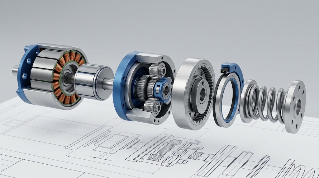
This technical cutaway illustrates a complete joint actuator assembly, highlighting the compact integration of an outrunner brushless DC motor, planetary reduction stages, precision angular position encoders, and compliant torque-sensing elements engineered for dynamic robotic platforms.
Actuation in One Minute
Every robot must obey the laws of physics. Motors generate torque, structures carry loads, and moving parts experience friction and inertia. These physical constraints determine what a robot can actually do.
- Actuators convert energy into motion: Motors transform electrical, fluidic, or chemical energy into mechanical movement.
- Mechanical structures carry loads: Links, joints, and frames must withstand operational stress and contact wrenches without excessive elastic deformation.
- Transmission systems modify torque and speed: Gearboxes allow high-speed, low-torque motors to drive heavy robotic joints smoothly.
- Inertia and friction resist motion: Robots must overcome mechanical impedance to accelerate and stop with sub-millimeter precision.
- Thermal limits restrict continuous operation: Ohmic Joule heating in windings limits sustained root-mean-square (RMS) torque output.
- Control algorithms depend on mechanical design: Predictable physical dynamics allow feedback controllers to stabilize aggressive trajectories without excitation of unmodeled structural resonances.
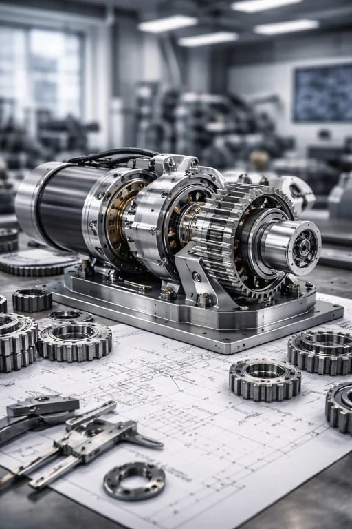
This precision actuator module illustrates the tightly packaged mechatronic integration in modern robotic joints. A high-torque brushless DC motor is coupled to a planetary or strain-wave gearbox, multiplying output torque while reducing shaft velocity. Embedded optical encoders provide dual-loop position feedback across the transmission, enabling precise closed-loop trajectory tracking under dynamic load variations.
Energy Conversion and Actuator Physics
An actuator is an energy transducer that converts stored electrical, hydraulic, or pneumatic energy into mechanical motion. In the vast majority of autonomous mobile robots and articulated manipulators, direct-current electromagnetic motors serve as the primary drive units.
Consider an electric actuator with applied terminal voltage \(V\) (Volts) drawing winding armature current \(I\) (Amperes). The electrical input power \(P_e\) is defined as:
$$P_e = V \cdot I$$The mechanical output power \(P_m\) delivered at the motor shaft is the product of shaft torque \(\tau\) (Newton-meters) and angular velocity \(\omega\) (radians per second):
$$P_m = \tau \cdot \omega$$The electromechanical conversion efficiency \(\eta\) represents the ratio of usable mechanical work to electrical power supplied:
$$\eta = \frac{P_m}{P_e} = \frac{\tau \cdot \omega}{V \cdot I}$$Energy losses occur primarily through winding copper resistance (\(I^2 R\) heating), core eddy currents, magnetic hysteresis, aerodynamic windage, and mechanical seal friction. Actuator selection requires evaluating the torque-speed curve, continuous thermal dissipation boundaries, torque density (\(\text{Nm/kg}\)), and mechanical back-drivability.
Torque, Speed, and Mechanical Power
Torque is the rotational analogue of linear force, generated when a force acts at a perpendicular distance from a rotational axis:
$$\tau = F \cdot r$$Where \(F\) is the normal applied force (Newtons) and \(r\) is the moment arm radius (meters). For continuous rotational motion, mechanical power delivered is:
$$P = \tau \cdot \omega = \tau \cdot \left(\frac{2\pi \cdot N}{60}\right)$$Where \(N\) is the shaft rotational speed in revolutions per minute (RPM).
Consider a single-link horizontal robotic arm holding a payload of mass \(m = 2.0\text{ kg}\) at the end of a rigid link of length \(L = 0.5\text{ m}\). Neglecting link self-weight, calculate the holding torque required at the shoulder joint.
Dynamic Effects and Rotational Inertia
When a robot transitions from rest to target velocity, the actuator must produce dynamic acceleration torque in addition to overcoming static gravity and friction. Newton-Euler rotational dynamics dictates:
$$\tau_{\text{dyn}} = I \cdot \alpha$$Where \(I\) is the mass moment of inertia about the axis of rotation (\(\text{kg}\cdot\text{m}^2\)) and \(\alpha\) is the angular acceleration (\(\text{rad/s}^2\)). For a concentrated point mass \(m\) located at radius \(r\):
$$I = m \cdot r^2$$For the payload in Example 1 (\(m = 2.0\text{ kg}\), \(r = 0.5\text{ m}\)), calculate the additional dynamic torque required to accelerate the joint at \(\alpha = 3.0\text{ rad/s}^2\), and compute total peak torque required during lift-off.
Transmission Systems and Gear Reduction
Electric servomotors operate most efficiently at high rotational speeds (\(2{,}000\) to \(8{,}000\text{ RPM}\)) while generating modest electromagnetic torque. Robotic links require low angular velocity with substantial torque. Mechanical transmissions bridge this mismatch.
The gear reduction ratio \(G\) (or \(N:1\)) is defined as:
$$G = \frac{\omega_{\text{motor}}}{\omega_{\text{joint}}} = \frac{N_{\text{output\_teeth}}}{N_{\text{input\_teeth}}}$$Under ideal conditions (100% mechanical efficiency), power is conserved (\(\tau_{\text{motor}} \omega_{\text{motor}} = \tau_{\text{joint}} \omega_{\text{joint}}\)). Accounting for mechanical transmission efficiency \(\eta_g < 1.0\), joint output torque becomes:
$$\tau_{\text{joint}} = G \cdot \eta_g \cdot \tau_{\text{motor}}$$Critically, the reflected inertia of the load seen by the motor rotor scales inversely with the square of the gear ratio:
$$I_{\text{reflected}} = \frac{I_{\text{load}}}{G^2}$$A brushless motor with nominal torque \(\tau_m = 1.2\text{ Nm}\) is coupled to a planetary transmission with reduction ratio \(G = 20\) and efficiency \(\eta_g = 0.90\) (\(90\%\)). Calculate the net joint torque and the reflected inertia of a load with \(I_L = 0.50\text{ kg}\cdot\text{m}^2\).
Actuation Challenges and Engineering Solutions
Modern robotics demands actuators that are simultaneously lightweight, highly dynamic, thermally resilient, and capable of safe physical interaction. Achieving these conflicting requirements introduces four primary engineering challenges:
The Challenge: Mechanical gear trains inherently possess clearance between mating gear teeth (backlash), manufacturing eccentricities, and transmission error. Backlash introduces a deadband in the control loop, causing limit-cycle oscillations, hunting, and end-effector positional hysteresis when direction reverses.
Technical Solutions:
- Strain-Wave (Harmonic) Gearing: Utilizes an elliptical wave generator inside an elastic flexspline, achieving zero-backlash meshing with continuous teeth engagement for high-ratio robotic joints.
- Dual-Encoder Feedback Architectures: Mounting high-resolution optical or magnetic encoders both on the motor input shaft and directly on the joint output link allows the controller to measure and cancel mechanical deflection and backlash in real time.
- Preloaded Cycloidal Drives: Uses rolling pin-and-cam configurations with negative tolerances to eliminate mechanical play while maintaining extreme shock-load capacity.
The Challenge: Electromagnetic torque scales linearly with armature current (\(\tau = K_t \cdot I\)), but resistive dissipation scales quadratically (\(P_{\text{loss}} = I^2 R\)). When robotic actuators maintain heavy static payloads or execute high-duty cycles, winding temperatures rapidly rise toward the Curie point of permanent magnets and insulation breakdown thresholds (\(\sim 155^\circ\text{C}\)–\(180^\circ\text{C}\)), severely capping continuous rated torque.
Technical Solutions:
- Quasi-Direct Drive (QDD) Topologies: Utilizing large-diameter, high pole-count outrunner motors paired with low-ratio planetary gearboxes (\(G \le 10:1\)) minimizes internal reflected inertia, maximizes mechanical efficiency, and allows the motor to operate at lower current per unit torque.
- Phase-Change Thermal Interface Materials and Conductive Heat Pipes: Integrating pyrolytic graphite sheets and active phase-change heat pipes routing thermal flux directly from stator teeth to the structural aluminum chassis of the robot.
- Model-Based Real-Time Thermal Observers: Executing lumped-parameter electro-thermal Kalman filters inside the motor drive firmware to predict winding core temperature without sensor latency, dynamically scaling current limits to maximize burst torque headroom.
The Challenge: Lightweight robotic links experience bending and torsional deflection under high acceleration. When high-ratio transmissions introduce joint compliance, the robot behaves as a multi-body flexible system. High-gain PID controllers inadvertently excite structural resonant frequencies, leading to destructive vibrations and limited trajectory tracking bandwidth.
Technical Solutions:
- Topology Optimization and Carbon-Fiber Composites: Employing finite element topology optimization (SIMP method) to allocate structural mass along principal stress vectors, producing monocoque structures with high specific stiffness (\(E/\rho\)).
- Input Shaping and Notch Filtering: Convolving trajectory velocity profiles with zero-vibration (ZV) or zero-vibration-derivative (ZVD) impulse sequences to ensure the motion profile injects zero spectral energy into structural resonance poles.
- Singular Perturbation Flexible-Joint Control: Decoupling the fast motor dynamics from the slow link deflection dynamics via two-time-scale singular perturbation theory, using torque-feedback damping loops to stabilize flexible joints.
The Challenge: High-ratio gearboxes exhibit extreme mechanical impedance and very high reflected inertia (\(I \propto G^2\)). If a high-ratio robotic arm collides with a rigid obstacle or human worker, the motor rotor cannot back-drive quickly enough, transmitting destructive impact forces directly through the gear teeth and to the human operator.
Technical Solutions:
- Series Elastic Actuation (SEA): Intentionally placing a calibrated mechanical spring in series between the gearbox output and the load. The spring decouples rotor inertia from impact shocks, stores elastic energy, and converts high-accuracy force control into a deflection measurement problem (\(F = k \cdot \Delta x\)).
- Variable Stiffness Actuators (VSA): Actuation systems featuring dual motors that independently modulate equilibrium position and mechanical joint stiffness online, enabling low stiffness during human contact and high stiffness during precision machining.
- Direct-Drive and High-Transparency Proprioception: Eliminating gearboxes entirely or using low ratios (\(G < 6\)) to maintain mechanical back-drivability, allowing the drive inverter to sense external contact forces directly through motor phase back-EMF and current sensing without requiring fragile wrist force-torque sensors.
Mechanical Structure and Load Distribution
The kinematic morphology of a robot establishes its geometric workspace, payload-to-weight ratio, stiffness, and dynamic equations:
- Serial Manipulators: Kinematic chains of open links connected in series. Offer large dexterous workspaces and accessibility, but accumulate positional errors, bending moments, and link mass along the chain.
- Parallel Manipulators (e.g., Stewart Platforms, Delta Robots): Closed kinematic loops where multiple actuators drive a shared end-effector. Yield exceptional structural stiffness, acceleration capabilities, and payload capacity, but possess restricted workspaces and complex forward kinematics.
- Wheeled Mobile Bases: Provide high energy efficiency on prepared surfaces; differential-drive and omnidirectional (Mecanum) platforms simplify planar trajectory control.
- Legged Robotic Platforms: Navigate unstructured, discontinuous terrain via isolated contact points, requiring continuous ground reaction force (GRF) optimization and high-frequency whole-body impulse control.
Compliance and Elastic Actuation
Modern collaborative and bio-inspired robots incorporate intentional mechanical elasticity to absorb physical impacts, store energy, and interact safely with unstructured environments. In an ideal linear elastic element, force is governed by Hooke's Law:
$$F = k \cdot x$$Where \(k\) is structural stiffness (\(\text{N/m}\)) and \(x\) is mechanical displacement (meters). In Series Elastic Actuators (SEAs), placing a spring of known stiffness \(k_s\) between the transmission and load yields joint output torque directly proportional to angular spring deflection \(\Delta\theta\):
$$\tau_{\text{joint}} = k_s \cdot (\theta_{\text{motor\_out}} - \theta_{\text{link}})$$This transforms closed-loop force control into an accurate position measurement problem, filtering shock loads and protecting delicate gearbox teeth during unexpected environmental collisions.
Thermal and Electrical Modeling
Actuator continuous output torque is strictly bounded by the thermal equilibrium of the motor armature. Electrical ohmic power loss dissipated as heat inside the winding coils is expressed as:
$$P_{\text{loss}} = I^2 R_a$$Where \(I\) is the root-mean-square current and \(R_a\) is the phase-to-phase armature resistance. The temperature increase \(\Delta T\) at steady state is governed by thermal resistance \(R_{\text{th}}\) (\(^\circ\text{C/W}\)) to the surrounding environment:
$$\Delta T = T_{\text{winding}} - T_{\text{ambient}} = P_{\text{loss}} \cdot R_{\text{th}} = (I^2 R_a) \cdot R_{\text{th}}$$Because torque is proportional to current (\(\tau = K_t \cdot I\)), doubling joint torque quadruples winding heat generation. Mechatronic designers must verify that the root-mean-square torque across an entire work cycle remains below the actuator's continuous thermal limit:
$$\tau_{\text{RMS}} = \sqrt{\frac{1}{T_{\text{cycle}}} \int_{0}^{T_{\text{cycle}}} \tau(t)^2 \, dt} \le \tau_{\text{continuous}}$$Application Contexts
- Industrial Robots: Prioritize structural stiffness, preloaded cycloidal gearing, and absolute repeatability to maintain sub-0.05 mm precision in automotive spot welding and machining.
- Surgical Robotics: Rely on zero-backlash capstan cable drives, brushless direct-drive motors, and micro-machined titanium linkages to deliver smooth, tremor-filtered telemanipulation.
- Legged Locomotion: Utilize low-ratio Quasi-Direct Drive (QDD) actuators with high torque transparency and low reflected inertia, absorbing high-frequency ground strike impulses passively.
- Collaborative Robots (Cobots): Integrate joint-level dual-channel torque sensors and series elastic compliance to satisfy ISO/TS 15066 transient human contact biomechanical limits.
- Soft Robotics: Deploy fluidic elastomer actuators (FEAs) and dielectric elastomers, achieving continuous morphological compliance for delicate agricultural harvesting and marine manipulation.
🎯 Career Guidance Tool Is Robotic Mechatronics & Mechanical Design Right For You?Explore mechanical design pathways, actuator engineering specializations, and mechatronic systems careers. | Explore Career Options → |
Foundational Knowledge and Curriculum Pathways
Students preparing for university-level mechatronics, actuation, and robotics design should develop competence across five interrelated engineering domains:
- Engineering Statics and Dynamics: Free-body equilibrium, multi-body Newtonian dynamics, and rotational inertia tensors.
- Mechanics of Materials: Stress-strain tensors, fatigue limits, structural deflection, and torsional stiffness.
- Electromechanical Systems: Magnetic circuit design, Lorenz force law, brushless drive commutation, and inverter electronics.
- Feedback Control Systems: State-space modeling, frequency-domain Bode analysis, and observer-based disturbance rejection.
- Computational CAD & FEA: Parametric 3D solid modeling, finite element stress analysis, and thermal simulation.
Interdisciplinary Robotics Architecture
Actuation and mechanical structures form the hardware foundation that translates software intelligence into physical force:
Actuation & Mechanical Design
Motors, precision gearboxes, series elastic mechanisms, and structural topologies that generate motion.
Robot Kinematics & Dynamics
Models how link geometries govern end-effector workspace, Jacobians, and multi-body equations of motion.
Sensors & Perception
Exteroceptive LiDAR, depth vision, tactile skins, and sensor fusion pipelines providing feedback to the system.
SLAM: Localization & Mapping
Constructs maps while tracking position using wheel odometry, visual odometry, and graph optimization.
Path Planning Algorithms
Computes collision-free trajectories in configuration space under kinematic and torque boundary constraints.
Advanced Control Systems
Implements computed torque, impedance control, and disturbance observers to drive physical motors reliably.
Conceptual Review & Self-Assessment Questions
1. How does a gearbox reduce the load inertia reflected back to an electric motor?
Answer: The load inertia reflected to the motor rotor shaft scales inversely with the square of the gear ratio (\(I_{\text{reflected}} = I_{\text{load}} / G^2\)). Consequently, a gear reduction of \(G = 10\) reduces the effective load inertia felt by the motor rotor by a factor of 100, allowing responsive control of large mechanical arms.
2. What is the fundamental operational trade-off of high gear ratios in robotic joints?
Answer: While high gear ratios amplify motor torque and downscale reflected load inertia, they introduce significant mechanical friction, increase gear backlash, introduce structural elasticity, and dramatically heighten the reflected rotor inertia seen by the environment (\(I_{\text{env}} = G^2 I_{\text{rotor}}\)). This high mechanical impedance severely degrades back-drivability and dynamic collision safety.
3. Why are Brushless DC (BLDC) motors preferred over brushed DC motors in robotic systems?
Answer: BLDC motors replace mechanical carbon brushes and commutators with electronic commutation via three-phase inverter switches. This design eliminates friction wear and arcing, improves thermal conductivity by locating stator windings on the outer housing, and provides significantly higher torque-to-weight ratios and operating lifespans.
4. What physical mechanism defines a Series Elastic Actuator (SEA)?
Answer: An SEA integrates an intentional, calibrated compliant elastic element (spring) positioned in series between the gearbox output and the robotic link. Joint torque is computed directly by measuring spring displacement (\(\tau = k_s \Delta\theta\)), decoupling rotor inertia from external impacts and providing passive shock tolerance.
5. Why does motor continuous torque differ drastically from peak stall torque?
Answer: Peak stall torque is constrained only by the maximum current the inverter can deliver and the magnetic saturation limit of the core steel, but it can only be sustained for seconds before the motor overheats. Continuous torque is strictly bounded by steady-state thermal equilibrium, where the rate of internal \(I^2 R\) resistive heat generation matches the thermal dissipation capacity of the motor housing.
Section 3: Numerical Engineering Problems & Solutions
A brushless DC robotic actuator operates from a DC bus voltage of \(V = 48\text{ V}\) and draws an armature current of \(I = 6.5\text{ A}\). The output shaft delivers a steady torque of \(\tau = 1.8\text{ Nm}\) at an angular velocity of \(\omega = 140\text{ rad/s}\). Calculate the electrical input power, mechanical output power, and overall transducer efficiency \(\eta\).
Compute electrical input power: $$P_e = V \cdot I = 48\text{ V} \times 6.5\text{ A} = 312.0\text{ W}$$ Compute mechanical output power delivered at the shaft: $$P_m = \tau \cdot \omega = 1.8\text{ Nm} \times 140\text{ rad/s} = 252.0\text{ W}$$ Calculate conversion efficiency: $$\eta = \frac{P_m}{P_e} = \frac{252.0}{312.0} \approx 0.8077 \Rightarrow 80.77\%$$ Final Answer: Mechanical output power is \(252.0\text{ W}\); efficiency is \(80.77\%\).
A robotic arm joint carries an external link and payload with a combined rotational inertia of \(I_L = 1.20\text{ kg}\cdot\text{m}^2\). The design engineer selects a motor with rotor inertia \(I_m = 3.0 \times 10^{-4}\text{ kg}\cdot\text{m}^2\). To achieve optimal dynamic power transfer, the reflected load inertia must match the motor rotor inertia (\(I_{\text{reflected}} = I_m\)). Calculate the ideal gear reduction ratio \(G\).
Formulate the reflected inertia relation: $$I_{\text{reflected}} = \frac{I_L}{G^2} = I_m$$ Rearrange to solve for gear ratio \(G\): $$G^2 = \frac{I_L}{I_m} \Rightarrow G = \sqrt{\frac{I_L}{I_m}}$$ Substitute the numerical values: $$G = \sqrt{\frac{1.20}{3.0 \times 10^{-4}}} = \sqrt{4000} \approx 63.25$$ Final Answer: An ideal inertia-matched transmission requires a gear ratio of approximately \(G \approx 63.25:1\).
A collaborative robot joint utilizes a Series Elastic Actuator with torsional spring constant \(k_s = 450\text{ Nm/rad}\). Optical encoders on the input and output sides of the spring measure an angular deflection of \(\Delta\theta = 2.4^\circ\). Calculate the instantaneous joint torque transmitted across the interface.
Convert the angular deflection from degrees to radians: $$\Delta\theta_{\text{rad}} = 2.4^\circ \times \left(\frac{\pi}{180^\circ}\right) = \frac{2.4 \times 3.14159}{180} \approx 0.041888\text{ rad}$$ Calculate joint torque via Hooke's torsional law: $$\tau = k_s \cdot \Delta\theta_{\text{rad}} = 450\text{ Nm/rad} \times 0.041888\text{ rad} = 18.85\text{ Nm}$$ Final Answer: Transmitted joint torque is \(18.85\text{ Nm}\).
An actuator motor features a phase armature resistance of \(R_a = 0.8\text{ }\Omega\) and a torque constant of \(K_t = 0.25\text{ Nm/A}\). The actuator produces a continuous holding torque of \(\tau = 2.5\text{ Nm}\). The total thermal resistance from winding to ambient air is \(R_{\text{th}} = 1.5\text{ }^\circ\text{C/W}\). Assuming an ambient temperature of \(T_{\text{amb}} = 25^\circ\text{C}\), calculate the steady-state winding temperature.
Determine the required armature current: $$I = \frac{\tau}{K_t} = \frac{2.5\text{ Nm}}{0.25\text{ Nm/A}} = 10.0\text{ A}$$ Compute the resistive thermal power loss: $$P_{\text{loss}} = I^2 R_a = (10.0\text{ A})^2 \times 0.8\text{ }\Omega = 100 \times 0.8 = 80.0\text{ W}$$ Compute the steady-state thermal rise: $$\Delta T = P_{\text{loss}} \cdot R_{\text{th}} = 80.0\text{ W} \times 1.5\text{ }^\circ\text{C/W} = 120.0^\circ\text{C}$$ Determine total core winding temperature: $$T_{\text{winding}} = T_{\text{amb}} + \Delta T = 25^\circ\text{C} + 120.0^\circ\text{C} = 145.0^\circ\text{C}$$ Final Answer: Steady-state winding temperature reaches \(145.0^\circ\text{C}\).
Actuation and Mechanical Design — Summary & Wrap-Up
Actuation and mechanical design constitute the indispensable physical medium of robotics. By mastering energy conversion metrics, transmission ratios, reflected inertia, structural resonance mitigation, and Series Elastic Actuation, mechatronics engineers build dynamic robotic hardware capable of safely applying force, executing precise trajectories, and withstanding the thermodynamic and mechanical stresses of real-world environments.