
1. Introduction & The Paradigm Shift in Mould Thermal Management
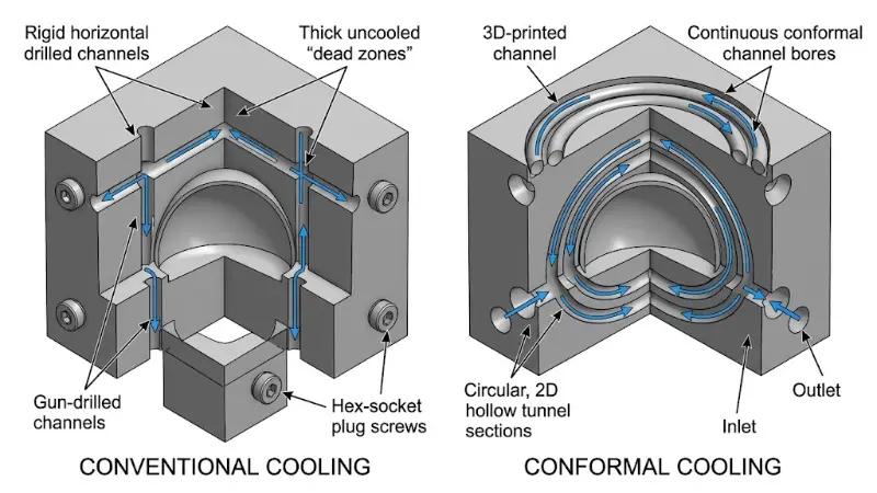
In high-volume polymer injection moulding, the cooling phase accounts for 60% to 80% of the total production cycle time. Conventional tooling manufacturing is constrained by subtractive computer numerical control (CNC) gun-drilling. Because linear gun-drilling can only produce straight, intersecting cylindrical bores, cooling lines inevitably pass at variable distances from complex, freeform part cavities. This geometric disconnect creates localized "dead zones" of high thermal mass, resulting in non-uniform heat flux, differential volumetric shrinkage, prolonged cycle times, and severe post-ejection part warpage.
Laser Powder Bed Fusion (LPBF) and Direct Metal Laser Sintering (DMLS) fundamentally eliminate the linear drill-path constraint. By building tooling inserts layer-by-layer from gas-atomized tool steel powders, engineers can route fluidic cooling conduits in arbitrary 3D space. Conformal cooling channels maintain an exact, equidistant offset from the contoured mould cavity surface, establishing uniform thermal gradients, homogenizing part crystallization kinetics, and reducing cooling cycle durations by 20% to 50%.
2. Conjugate Heat Transfer & Governing Equations
Accurate thermal modeling of a conformal cooling system requires solving a coupled conjugate heat transfer problem combining transient multidimensional conduction within the solid steel mould insert and forced convective heat transfer in the turbulent liquid coolant conduit.
2.1 Transient Thermal Conduction
Within the solid metallic insert, transient temperature evolution \(T(\mathbf{x}, t)\) is governed by the Fourier heat conduction equation:
$$\rho_m c_p \frac{\partial T}{\partial t} = \nabla \cdot (k_m \nabla T)$$where \(\rho_m\) is the density of the tooling material (\(\text{kg/m}^3\)), \(c_p\) is the specific heat capacity (\(\text{J}/(\text{kg}\cdot\text{K})\)), and \(k_m\) is the temperature-dependent thermal conductivity (\(\text{W}/(\text{m}\cdot\text{K})\)). For maraging steel 18Ni300 (1.2709), \(k_m \approx 20\text{ W}/(\text{m}\cdot\text{K})\) in the as-built state and increases to approximately \(24\text{ W}/(\text{m}\cdot\text{K})\) following age hardening.
2.2 Convective Heat Transfer & Fluid Turbulence
The local heat flux \(q''\) extracted from the channel wall into the coolant fluid is dictated by Newton's Law of Cooling:
$$q'' = h \cdot (T_{\text{wall}} - T_{\text{bulk}})$$Maximizing the convective heat transfer coefficient \(h\) requires operating within the fully developed turbulent flow regime. The transition to turbulence is characterized by the dimensionless Reynolds number (\(Re\)):
$$Re = \frac{\rho_f \cdot v \cdot D_h}{\mu_f} = \frac{v \cdot D_h}{\nu_f}$$where \(\rho_f\) is fluid density, \(v\) is mean flow velocity, \(D_h\) is the hydraulic diameter, \(\mu_f\) is dynamic viscosity, and \(\nu_f\) is kinematic viscosity. For internal pipe flow:
- Laminar Flow: \(Re < 2300\) (yielding poor convective dissipation and thick thermal boundary layers).
- Transitional Flow: \(2300 \le Re \le 4000\).
- Turbulent Flow: \(Re > 4000\) (industry target for conformal tooling: \(Re \ge 10\,000\) to maintain robust mixing without cavitation).
For fully developed turbulent flow in smooth channels, the Nusselt number (\(Nu\)) is computed via the empirical Dittus-Boelter correlation (for heating of the cooling fluid):
$$Nu = 0.023 \cdot Re^{0.8} \cdot Pr^{0.4}$$where the Prandtl number \(Pr = \frac{c_f \mu_f}{k_f}\). The resulting convective coefficient \(h\) is:
$$h = \frac{Nu \cdot k_f}{D_h}$$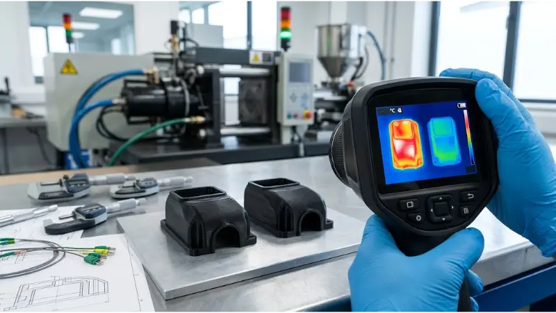
3. Hydraulic Pressure Drop & Friction Head Loss
While increasing fluid velocity elevates \(Re\) and \(h\), it exponentially increases hydraulic pressure drop (\(\Delta P\)), demanding larger auxiliary pump work and risking mold seal blowouts. Total pressure drop across a conformal cooling circuit is calculated by the Darcy-Weisbach formulation:
$$\Delta P = f \cdot \frac{L}{D_h} \cdot \frac{\rho_f v^2}{2} + \sum K_i \cdot \frac{\rho_f v^2}{2}$$where \(L\) is the total channel length, \(K_i\) represents minor loss coefficients for curved bends and elbows, and \(f\) is the Darcy friction factor. In LPBF printed channels, surface roughness (\(Ra\)) is naturally higher than in drilled steel (\(Ra \approx 10\text{--}25\,\mu\text{m}\) as-printed). The friction factor is determined via the Colebrook-White implicit relationship:
$$\frac{1}{\sqrt{f}} = -2.0 \log_{10} \left( \frac{\varepsilon / D_h}{3.7} + \frac{2.51}{Re \sqrt{f}} \right)$$where \(\varepsilon\) is the equivalent sand-grain surface roughness. Elevated as-printed roughness trips turbulence at lower Reynolds numbers, enhancing heat transfer, but must be balanced against pumping head limitations.
Interactive Engineering Tool: Conformal Cooling Hydro-Thermal Calculator
Calculate Reynolds Number (\(Re\)), convective heat transfer coefficient (\(h\)), and estimated Darcy pressure drop (\(\Delta P\)) for water at 20°C (\(\rho = 998\,\text{kg/m}^3\), \(\mu = 1.002\times 10^{-3}\,\text{Pa}\cdot\text{s}\), \(k_f = 0.598\,\text{W/m}\cdot\text{K}\), \(Pr = 7.01\)).
4. Design for Additive Manufacturing (DfAM) Tooling Rules
Producing functional conformal tooling via LPBF demands strict geometric constraints to prevent build failures, powder entrapment, and premature stress cracking during high-pressure injection cycling.
| Design Parameter | Recommended Value | Engineering Rationale & Failure Mode |
|---|---|---|
| Channel Diameter (\(D_h\)) | \(4.0 - 12.0\,\text{mm}\) | Below 4 mm risks powder depowdering clogs; above 12 mm leads to downward surface sag and lack-of-fusion defects without supports. |
| Cavity-to-Channel Offset (\(L_w\)) | \(1.5 \times D_h - 2.0 \times D_h\) (\(\ge 3.0\,\text{mm}\)) | Prevents mechanical wall deflection under injection clamp tonnages (up to 200 MPa) and cyclic thermal fatigue cracking. |
| Inter-Channel Pitch (\(P\)) | \(2.0 \times D_h - 3.0 \times D_h\) | Ensures uniform temperature distribution along the tool face and avoids localized thermal dead bands. |
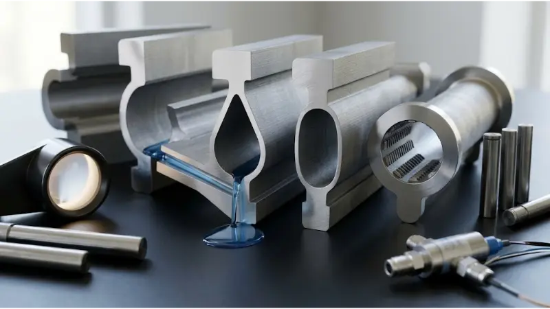
| Cross-Section Profile | Teardrop, Elliptical, Diamond | Angles exceeding \(45^\circ\) from horizontal allow self-supporting builds without internal support structures. |
| Corner Radius (\(R_{\min}\)) | \(\ge 1.5 \times D_h\) | Minimizes minor hydraulic losses (\(K_i\)) and reduces localized hydrodynamic cavitation erosion. |
Any trapped unmelted metal powder inside conformal circuits acts as an insulator, restricts coolant flow, and causes downstream blockage in chiller manifolds. Tooling inserts must undergo post-build dry acoustic depowdering, chemical/abrasive flow machining (AFM) to deburr internal channel surfaces, and full Solution Annealing + Age Hardening heat treatment (\(480\text{--}490^\circ\text{C}\) for 6 hours) to achieve \(50\text{--}54\,\text{HRC}\) toughness.
5. Pedagogical Summary & Washington Accord Alignment
Mastery of 3D-printed dies and conformal cooling provides practical evidence of several key Washington Accord and EUR-ACE professional competencies:
- WA1 (Engineering Knowledge): Synthesis of advanced fluid mechanics (Navier-Stokes, Dittus-Boelter heat transfer) with metallurgical principles of laser powder bed fusion.
- WA2 (Problem Analysis): Identifying thermal bottlenecks and transient temperature differentials causing warpage in industrial manufacturing processes.
- WA3 (Design/Development of Solutions): Formulating complete DfAM parameters (cross-sectional geometry, channel pitch, wall offset) that meet thermal dissipation targets while withstanding cyclical injection pressure.
- WA5 (Modern Tool Usage): Integrating computational fluid dynamics (CFD), finite element analysis (FEA), and infrared metrology to validate injection mould inserts.