
Aerial robotics represents one of the most dynamically demanding branches of modern robotics. Unlike ground-based systems, unmanned aerial vehicles (UAVs) must maintain stability in three-dimensional space while continuously compensating for gravity, aerodynamic forces, and environmental disturbances such as wind gusts. The challenge is not merely computational — it is fundamentally physical.
Aerial robotic systems integrate lightweight mechanical design, high-frequency control loops, inertial sensing, aerodynamic modeling, and real-time trajectory planning. They are prime examples of cyber-physical systems in which software algorithms directly stabilize inherently unstable mechanical dynamics.
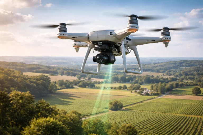
Aerial robotics studies the engineering of unmanned aerial vehicles (UAVs) capable of controlled flight in three-dimensional space. The drone shown represents a quadrotor system in which four propellers generate thrust and torque to stabilize and maneuver the vehicle through the air. Using onboard sensors such as inertial measurement units (IMUs), GPS receivers, cameras, and altitude sensors, the UAV continuously estimates its position and orientation while adjusting motor speeds hundreds of times per second to maintain stable flight.
Interactive Quick Review: Core Flight Fundamentals
Test your understanding of basic hover mechanics and six-degrees-of-freedom flight dynamics before exploring advanced modeling equations:
1. What physical condition must be met for a UAV to hover at a constant altitude?
Answer: The total upward thrust generated by the vehicle's propellers must exactly balance the downward gravitational force acting on its mass (\(T = mg\)).
2. What are the six degrees of freedom (6-DOF) associated with aerial robotic movement in three-dimensional space?
Answer: Three translational motions along the \(x, y, z\) orthogonal spatial axes and three rotational orientations about the body axes known as roll (\(\phi\)), pitch (\(\theta\)), and yaw (\(\psi\)).
Basic Flight Mechanics
For a multirotor UAV to hover at a static altitude in calm air, the net vertical aerodynamic thrust produced across all rotor actuators must precisely equal the total vehicle gravitational force:
$$T = mg$$- \(T\): Total upward collective thrust generated across all propellers (Newtons).
- \(m\): Total flight mass of the UAV including airframe, avionics, and payload (\(\text{kg}\)).
- \(g \approx 9.81\text{ m/s}^2\): Gravitational acceleration constant.
Consider a standard quadrotor with a total all-up mass of \(m = 1.50\text{ kg}\). Calculate the total collective hover thrust required and the baseline thrust generated by each individual motor unit.
Six Degrees of Freedom (6-DOF) Kinematics
Aerial robotic systems maneuver unconstrained in three-dimensional space, possessing six degrees of freedom comprising position \(\mathbf{p} = \begin{bmatrix} x & y & z \end{bmatrix}^T \in \mathbb{R}^3\) and attitude orientation defined by the rotation matrix \(\mathbf{R} \in SO(3)\):
- Roll (\(\phi\)): Rotation about the vehicle's longitudinal forward axis (\(x_B\)).
- Pitch (\(\theta\)): Rotation about the vehicle's transverse lateral axis (\(y_B\)).
- Yaw (\(\psi\)): Rotation about the vehicle's normal vertical axis (\(z_B\)).
The orientation matrix \(\mathbf{R}_{B}^{W}\) maps body-fixed frame coordinates (\(B\)) into the inertial world frame (\(W\)) using the \(Z\)-\(Y\)-\(X\) Euler sequence:
$$\mathbf{R} = \mathbf{R}_z(\psi) \mathbf{R}_y(\theta) \mathbf{R}_x(\phi)$$Translational Dynamics
The translational acceleration of the UAV center of mass is governed by Newton's Second Law formulated in the inertial frame:
$$m \mathbf{\ddot{p}} = \mathbf{R} \mathbf{T}_B - m \mathbf{g}_W - \mathbf{D}_t \mathbf{\dot{p}}$$- \(\mathbf{\ddot{p}} = \begin{bmatrix} \ddot{x} & \ddot{y} & \ddot{z} \end{bmatrix}^T\): Linear acceleration vector in the world frame.
- \(\mathbf{T}_B = \begin{bmatrix} 0 & 0 & T \end{bmatrix}^T\): Collective thrust vector directed along the body \(z_B\)-axis.
- \(\mathbf{g}_W = \begin{bmatrix} 0 & 0 & g \end{bmatrix}^T\): Gravitational acceleration vector in the world frame.
- \(\mathbf{D}_t\): Translational aerodynamic drag coefficient diagonal matrix.
Because thrust is fixed along the body \(z_B\)-axis, quadrotors are underactuated: translational motion along the horizontal plane requires tilting the vehicle attitude (\(\phi\) or \(\theta\)) to project a horizontal component of thrust.
Rotational (Attitude) Dynamics
The rotational acceleration of the airframe about its center of mass is governed by Euler's rotational equations for rigid bodies:
$$\mathbf{I} \mathbf{\dot{\omega}} + \boldsymbol{\omega} \times (\mathbf{I} \boldsymbol{\omega}) = \boldsymbol{\tau}_B$$- \(\mathbf{I} = \text{diag}(I_{xx}, I_{yy}, I_{zz})\): Principal inertia tensor matrix of the vehicle (\(\text{kg}\cdot\text{m}^2\)).
- \(\boldsymbol{\omega} = \begin{bmatrix} p & q & r \end{bmatrix}^T\): Angular velocity vector expressed in the body frame (\(\text{rad/s}\)).
- \(\boldsymbol{\omega} \times (\mathbf{I} \boldsymbol{\omega})\): Gyroscopic cross-coupling torque arising during multi-axis maneuvers.
- \(\boldsymbol{\tau}_B = \begin{bmatrix} \tau_\phi & \tau_\theta & \tau_\psi \end{bmatrix}^T\): Control torque vector generated by differential rotor speeds.
A quadrotor has roll-axis moment of inertia \(I_{xx} = 0.020\text{ kg}\cdot\text{m}^2\). A differential thrust command across the lateral motors generates a net roll torque of \(\tau_\phi = 0.010\text{ Nm}\). Assuming negligible cross-coupling at hover, calculate the roll angular acceleration \(\dot{p}\).
Motor Thrust and Torque Generation
Propellers generate aerodynamic lift and reaction drag proportional to the square of motor rotational velocity \(\omega_i\) (rad/s):
$$T_i = k_f \omega_i^2 \quad \text{and} \quad Q_i = k_m \omega_i^2$$Where \(k_f\) is the aerodynamic thrust coefficient and \(k_m\) is the drag torque coefficient. For a quadrotor in an 'X' configuration with arm length \(d\), the control allocation mapping is:
$$\begin{bmatrix} T \\ \tau_\phi \\ \tau_\theta \\ \tau_\psi \end{bmatrix} = \begin{bmatrix} k_f & k_f & k_f & k_f \\ -\frac{\sqrt{2}}{2} d k_f & -\frac{\sqrt{2}}{2} d k_f & \frac{\sqrt{2}}{2} d k_f & \frac{\sqrt{2}}{2} d k_f \\ \frac{\sqrt{2}}{2} d k_f & -\frac{\sqrt{2}}{2} d k_f & -\frac{\sqrt{2}}{2} d k_f & \frac{\sqrt{2}}{2} d k_f \\ k_m & -k_m & k_m & -k_m \end{bmatrix} \begin{bmatrix} \omega_1^2 \\ \omega_2^2 \\ \omega_3^2 \\ \omega_4^2 \end{bmatrix}$$Yaw torque \(\tau_\psi\) is generated entirely through the aerodynamic reaction torque difference between clockwise and counter-clockwise spinning pairs.
Aerial Robotics Challenges and Engineering Solutions
Deploying autonomous aerial vehicles in dynamic, unstructured outdoor environments introduces severe coupled physical and algorithmic constraints. Below are four primary technical challenges and their engineering mitigation frameworks:
The Challenge: Multirotors operate within turbulent atmospheric boundary layers. Unsteady crosswinds inject non-conservative aerodynamic drag, while proximity to surfaces creates the "ground effect"—compressing rotor downwash into high-pressure air cushions that destabilize precision hover during takeoff, landing, and perch-and-stare operations.
- Nonlinear Adaptive Control and \(L_1\) Adaptive Architectures: Decoupling estimation from control adaptation to rapidly estimate and cancel high-frequency wind gust disturbances without destabilizing the phase margin.
- Incremental Nonlinear Dynamic Inversion (INDI): Replacing full aerodynamic model dependence by utilizing high-rate IMU angular acceleration measurements to instantly cancel wind disturbances at the motor drive level.
- Ground Effect Empirical Lookups: Integrating Cheeseman-Bennett ground effect correction factors (\(T/T_\infty = \frac{1}{1 - (R/4z)^2}\)) into altitude feedforward compensation loops.
The Challenge: Operating in subterranean mines, dense urban canyons, or indoor industrial facilities eliminates satellite GPS coverage. Conventional vision-based SLAM systems fail under motion blur during aggressive flight maneuvers, low lighting, or textureless corridors.
- Visual-Inertial Odometry (VIO) with Preintegration: Tightly fusing high-rate IMU delta measurements with sparse visual feature tracks using optimization factor graphs (e.g., GTSAM / VINS-Mono).
- Neuromorphic Event Cameras: Utilizing microsecond asynchronous event sensors that measure brightness changes rather than full frames, eliminating motion blur during rapid agile rotations.
- Solid-State LiDAR Odometry: Integrating ultra-lightweight solid-state LiDAR (e.g., FAST-LIO) to maintain centimeter-level 3D localization drift-free in total darkness.
The Challenge: Rotorcraft energy consumption scales steeply with gross takeoff weight. Batteries exhibit low specific energy density (\(\sim 250\text{ Wh/kg}\) for LiPo), limiting operational endurance to 20–40 minutes while forcing harsh compromises between onboard sensor payloads and flight time.
- Carbon-Fiber Monocoque Aerostructures: Employing hollow carbon-fiber composite frames and integrated PCB arms to maximize structural rigidity per gram.
- Edge Tensor Processing Units (NPUs): Deploying low-power edge accelerators (e.g., 5–15W systems) executing quantized neural networks for real-time semantic obstacle avoidance.
- Hybrid-Electric and Tethered Systems: Utilizing tethered micro-cables for indefinite stationary surveillance, or gas-electric range extenders for extended missions.
The Challenge: A conventional quadrotor has four actuator inputs to control four independent outputs (\(T, \tau_\phi, \tau_\theta, \tau_\psi\)). If one motor or ESC fails mid-flight, the system loses controllability: yaw reaction torque becomes unmanageable, causing the craft to enter an uncontrolled high-speed spin and crash.
- Degraded Attitude Periodic Spin Control: Sacrificing yaw stabilization deliberately—allowing the drone to spin continuously about its primary axis at high angular rate while utilizing the remaining three operational rotors to stabilize position and land safely.
- Hexarotor / Octorotor Overactuation: Designing airframes with redundant co-axial or planar motor pairs, allowing control allocation algorithms to isolate failed actuators without degrading flight envelope.
- Automatic Parachute Ballistic Recovery: Integrating pyrotechnic spring-loaded parachutes triggered by onboard IMU tumble detection algorithms in under \(100\text{ ms}\).
Sensory Perception and Extended Kalman Filter State Estimation
Because aerial robots move rapidly through 3D space, raw sensor data from IMUs (accelerometers, gyroscopes) suffers from integration drift, while GPS measurements suffer from low update rates (\(5\text{–}10\text{ Hz}\)) and multipath reflections. The Error-State Extended Kalman Filter (ES-EKF) fuses these complementary data streams:
In the measurement update step, the innovation residual between actual sensor observation \(\mathbf{z}_k\) and predicted measurement \(\mathbf{h}(\mathbf{\hat{x}}_{k|k-1})\) is scaled by the optimal Kalman gain \(\mathbf{K}_k\):
$$\mathbf{\hat{x}}_{k|k} = \mathbf{\hat{x}}_{k|k-1} + \mathbf{K}_k \left(\mathbf{z}_k - \mathbf{H} \mathbf{\hat{x}}_{k|k-1}\right)$$Where \(\mathbf{K}_k = \mathbf{P}_{k|k-1} \mathbf{H}^T (\mathbf{H} \mathbf{P}_{k|k-1} \mathbf{H}^T + \mathbf{V})^{-1}\), with \(\mathbf{P}\) denoting error covariance and \(\mathbf{V}\) representing measurement noise covariance.
Minimum Snap Trajectory Generation
Because quadrotor translational motion is coupled to orientation through its fourth derivative of position, smooth trajectory planning requires minimizing Snap (the second derivative of acceleration):
$$\min_{\mathbf{p}(t)} \int_0^T \left\|\frac{d^4 \mathbf{p}(t)}{dt^4}\right\|^2 dt = \min_{\mathbf{p}(t)} \int_0^T \|\mathbf{p}^{(4)}(t)\|^2 dt$$Parameterizing trajectories as piecewise polynomial splines ensures that motor angular accelerations and rotor thrust commands remain continuous and bounded within physical motor torque constraints.
Battery Energy and Flight Endurance Constraints
Flight endurance is strictly bounded by onboard battery capacity and motor electromechanical efficiency. Total endurance is modeled as:
$$t_{\text{flight}} = \frac{E_{\text{battery}} \cdot \eta_{\text{discharge}}}{P_{\text{hover}} + P_{\text{avionics}}}$$Where \(E_{\text{battery}}\) is total stored energy (\(\text{Wh}\)), \(\eta_{\text{discharge}} \approx 0.80\) represents battery depth-of-discharge safety margin, and \(P_{\text{hover}}\) is electrical power consumed during hover.
A surveillance quadrotor carries a \(4\text{S}\) lithium battery pack rated at \(E = 150\text{ Wh}\). The total average power drawn by the four propulsion motors and onboard computer during cruise is \(P = 250\text{ W}\). Assuming an \(80\%\) maximum depth-of-discharge reserve, calculate the mission flight duration.
🎯 Career Guidance Tool Is Aerial Robotics & UAV Systems Right For You?Explore aerospace guidance engineering pathways, flight control systems careers, and autonomous drone navigation. | Explore Career Options → |
Interactive Quick Review: Dynamics, State Estimation & Planning
Reinforce key concepts regarding 6-DOF dynamics, sensor fusion, and energy constraints before reviewing the FAQ:
1. Why do multirotor UAV attitude control loops require high update frequencies between 200 and 1000 Hz?
Answer: Because aerial vehicles are naturally unstable mechanical systems with small rotational inertias, requiring millisecond-level feedback loops to reject high-frequency aerodynamic turbulence and prevent divergent tumble.
2. What is the primary operational role of state estimation techniques like the Kalman filter in UAV navigation?
Answer: To statistically combine high-frequency, noisy IMU inertial updates with lower-rate absolute reference signals (GPS, barometric altimeter, optical flow), providing an optimal, drift-free estimate of position, velocity, and attitude.
Frequently Asked Questions about Aerial Robotics and UAV Systems
What is aerial robotics, and how does it differ from ground robotics?
Aerial robotics focuses on unmanned systems capable of controlled autonomous flight in three-dimensional space. Unlike ground robots, which remain stably supported by terrain, aerial robots are underactuated, open-loop unstable machines that require continuous active thrust balancing to prevent falling.
Why are quadrotors widely used in aerial robotics research?
Quadrotors use four fixed-pitch propellers with no complex mechanical swashplates or linkages. Maneuvering relies entirely on electronic motor speed variation, providing an ideal, mathematically clean physical platform for validating nonlinear control algorithms and state estimators.
How do UAVs navigate when GPS signals are unavailable?
In GPS-denied settings (subterranean spaces, inside buildings, or dense forest canopies), UAVs utilize onboard Visual-Inertial Odometry (VIO) or LiDAR SLAM, tracking visual point features or laser returns relative to their surroundings to compute real-time position drift-free.
What mathematical and physical principles are most important for studying aerial robotics?
Core requirements include Newton-Euler rigid-body mechanics, spatial rotation algebra in \(SO(3)\), multi-variable state-space feedback control (PID, LQR, Geometric SE(3) tracking), probabilistic Kalman filtering, and convex trajectory optimization.
End-of-Page Exercises: Review, Thought-Provoking & Engineering Problems
Section 1: Foundational Review Questions & Answers
1. What equilibrium condition must be satisfied for a quadrotor UAV to maintain hover at constant altitude?
Answer: Total collective propeller thrust must equal gravitational force: \(T = mg\), with the body thrust vector oriented collinearly with gravity.
2. What are the six degrees of freedom (6-DOF) that define rigid-body movement in three-dimensional space?
Answer: Three translational coordinates (\(x, y, z\)) defining spatial position in the inertial frame and three rotational angles (roll \(\phi\), pitch \(\theta\), yaw \(\psi\)) defining body orientation.
3. How does tilting a multirotor UAV's body frame generate translational acceleration along the horizontal plane?
Answer: Tilting the craft rotates the thrust vector away from vertical, projecting a horizontal force component (\(F_x = T \sin\theta\)) that accelerates the center of mass laterally.
4. What physical phenomenon causes yaw rotation in a quadrotor helicopter?
Answer: Aerodynamic drag reaction torques generated by spinning propellers. Increasing speed in clockwise motors while decreasing speed in counter-clockwise motors creates a net reactive yaw torque about the vertical axis.
5. What is the primary function of a Kalman filter within a UAV state estimation pipeline?
Answer: To statistically combine high-frequency, noisy IMU accelerometer/gyroscope signals with low-frequency sensor corrections (GPS, vision, barometer), minimizing state estimation covariance.
6. Why do UAV attitude control loops typically execute at high update frequencies (200 to 1000 Hz)?
Answer: High update rates are required because rotational dynamics are extremely fast and inherently unstable, necessitating rapid motor adjustments to maintain attitude stability under wind gusts.
7. How does propeller thrust relate mathematically to motor rotational speed?
Answer: Propeller thrust scales quadratically with motor angular velocity: \(T_i = k_f \omega_i^2\), where \(k_f\) is the empirical aerodynamic thrust coefficient.
8. What physical parameters limit the maximum flight endurance of battery-powered autonomous drones?
Answer: Battery chemical specific energy density (\(\text{Wh/kg}\)) versus all-up aircraft weight, coupled with rotor aerodynamic efficiency (thrust per electrical Watt).
9. What role do gyroscopic coupling terms play in rigid-body rotational dynamics?
Answer: Represented by \(\boldsymbol{\omega} \times (\mathbf{I} \boldsymbol{\omega})\), they capture the cross-axis inertial interactions that induce precession torques when rotating across multiple spatial axes simultaneously.
10. How do trajectory planning algorithms optimize flight paths for autonomous UAVs?
Answer: By minimizing higher-order trajectory derivatives—specifically snap—using piecewise polynomial curves that ensure motor acceleration bounds are strictly respected.
Section 2: Analytical & Thought-Provoking Questions
1. How do ground effect turbulence zones near surfaces alter UAV height control during landing?
Answer: Close to the ground, downwash vortices cannot expand freely and compress against the ground plane. This increases rotor thrust per Watt, causing standard PID altitude controllers to float or bounce unexpectedly during touchdown.
2. What fundamental control challenges arise when a quadrotor loses a propeller motor mid-flight?
Answer: Quadrotors are underactuated. Losing one rotor destroys yaw moment equilibrium. The control system must sacrifice yaw regulation entirely, allowing the craft to spin continuously along its primary axis while maintaining vertical thrust to land safely.
3. Why is visual SLAM computationally heavier on aerial drones than on ground rovers?
Answer: Drones move through full 6-DOF with rapid pitch and roll variations, requiring 3D volumetric mapping rather than 2D planar occupancy grids, while carrying strict SWaP computing constraints.
4. How do wind gusts and atmospheric turbulence invalidate simplified linear flight control models?
Answer: Wind generates nonlinear asymmetric drag and blade flapping torques that vary with apparent airspeed. These disturbance wrenches push the vehicle far beyond the small-angle assumptions of linear PID models.
5. What safety and regulatory dilemmas emerge when autonomous delivery drones operate in urban airspace?
Answer: Risks include mid-air collisions, acoustic pollution, loss-of-link flight termination above crowds, and third-party ground liability, necessitating formal fail-safe certifiable airworthiness standards.
6. How can insect-inspired flapping-wing aerial vehicles outperform quadrotors in micro-scale indoor flight?
Answer: Flapping-wing mechanisms operate at low Reynolds numbers, exploiting leading-edge vortex lift mechanisms that provide extreme agility, safe physical interaction with walls, and high aerodynamic efficiency at sub-gram scales.
7. What compromises occur when balancing onboard embedded compute weight against flight endurance?
Answer: High-performance GPUs enable dense neural network depth estimation but add structural mass and draw tens of Watts of continuous power, drastically cutting available flight battery runtime.
8. How does tethered power supply architecture transform operational capabilities for inspection drones?
Answer: Ground-tethered high-voltage lines provide continuous, unlimited electrical power for multi-day monitoring, trading spatial mobility for persistence and safety.
9. What limitations affect optical flow state estimation during low-texture or nighttime flight?
Answer: Optical flow requires high spatial contrast gradients to track motion vectors between frames. In dark, reflective, or homogeneous environments, optical flow algorithms experience tracking loss, resulting in position drift.
10. How do distributed multi-agent swarm control protocols handle communication dropouts?
Answer: Multi-agent swarms use consensus rules and artificial potential fields that rely solely on localized line-of-sight distance sensors, maintaining cohesion and collision avoidance without centralized radio contact.
11. What distinguishes momentum-based collision detection from traditional tactile bumper sensors?
Answer: Momentum observers monitor discrepancies between commanded rotor speeds and dynamic IMU responses, estimating collision wrenches instantly across the entire airframe without physical switches.
12. How does aerodynamic drag at high cruising speeds limit multirotor efficiency compared to fixed-wing aircraft?
Answer: Multirotors must pitch forward aggressively to generate forward thrust, forcing rotors to fight profile drag, whereas fixed-wing aircraft generate passive aerodynamic lift via wing airfoils.
Section 3: Numerical Engineering Problems & Solutions
A quadrotor UAV has a total mass of \(m = 2.40\text{ kg}\). Assuming standard gravitational acceleration \(g = 9.81\text{ m/s}^2\), calculate the total thrust force required for static hover and the required thrust output per motor assuming equal distribution.
Calculate total hover thrust: $$T = mg = 2.40\text{ kg} \times 9.81\text{ m/s}^2 = 23.544\text{ N}$$ Compute individual motor thrust across 4 symmetric rotors: $$T_i = \frac{T}{4} = \frac{23.544\text{ N}}{4} = 5.886\text{ N}$$ Final Answer: Total hover thrust is \(23.54\text{ N}\); each motor must produce \(5.89\text{ N}\).
A quadrotor has a roll-axis moment of inertia \(I_{xx} = 0.025\text{ kg}\cdot\text{m}^2\). If a differential motor thrust command generates a net roll torque \(\tau_\phi = 0.015\text{ Nm}\), calculate the resulting angular acceleration \(\dot{p}\) about the roll axis.
Apply Euler's rotational equation for single-axis acceleration: $$\dot{p} = \frac{\tau_\phi}{I_{xx}}$$ Substitute numerical values: $$\dot{p} = \frac{0.015\text{ Nm}}{0.025\text{ kg}\cdot\text{m}^2} = 0.60\text{ rad/s}^2$$ Final Answer: Resulting angular acceleration is \(0.60\text{ rad/s}^2\).
A brushless motor drives a propeller with a thrust coefficient \(k_f = 1.20 \times 10^{-8}\text{ N/(rad/s)}^2\). Calculate the thrust generated when the propeller spins at an angular speed of \(\omega_i = 6{,}000\text{ RPM}\).
Convert shaft rotational speed to radians per second: $$\omega_i = 6000\text{ RPM} \times \left(\frac{2\pi}{60}\right) = 6000 \times 0.1047198 \approx 628.3185\text{ rad/s}$$ Apply aerodynamic thrust equation: $$T_i = k_f \omega_i^2 = (1.20 \times 10^{-8}) \times (628.3185)^2$$ $$T_i = (1.20 \times 10^{-8}) \times 394{,}784.18 \approx 4.7374\text{ N}$$ Final Answer: Propeller thrust is approximately \(4.74\text{ N}\).
An autonomous drone carries a lithium-polymer battery pack with stored energy capacity \(E = 150.0\text{ Wh}\). During mapping operations, the average electrical power consumption is \(P = 250.0\text{ W}\). Calculate the estimated maximum flight duration in hours and minutes.
Formulate flight time ratio: $$t_{\text{flight}} = \frac{E}{P} = \frac{150.0\text{ Wh}}{250.0\text{ W}} = 0.60\text{ hours}$$ Convert fractional hours to minutes: $$t_{\text{flight}} = 0.60\text{ hours} \times 60\text{ minutes/hour} = 36.0\text{ minutes}$$ Final Answer: Flight duration is \(0.60\text{ hours}\) (\(36\text{ minutes}\)).
A UAV altitude estimator predicts an a priori height of \(\hat{z}_{k|k-1} = 50.0\text{ m}\). A barometric sensor measurement reads \(z_k = 50.50\text{ m}\). If the Kalman gain is \(K_k = 0.35\) with observation matrix \(H = 1\), calculate the updated posterior state estimate \(\hat{z}_{k|k}\).
Compute innovation residual: $$\tilde{y}_k = z_k - H \hat{z}_{k|k-1} = 50.50\text{ m} - 50.0\text{ m} = 0.50\text{ m}$$ Apply the Kalman update equation: $$\hat{z}_{k|k} = \hat{z}_{k|k-1} + K_k \tilde{y}_k = 50.0 + (0.35 \times 0.50) = 50.0 + 0.175 = 50.175\text{ m}$$ Final Answer: Updated posterior altitude estimate is \(50.18\text{ meters}\).
A quadrotor has a yaw drag torque coefficient \(k_m = 1.50 \times 10^{-9}\text{ Nm/(rad/s)}^2\). Clockwise motors 1 and 3 spin at \(\omega_{1,3} = 5{,}500\text{ RPM}\), while counter-clockwise motors 2 and 4 spin at \(\omega_{2,4} = 5{,}300\text{ RPM}\). Calculate the net reaction yaw torque \(\tau_\psi\).
Convert angular speeds from RPM to rad/s: $$\omega_{1,3} = 5500 \times \left(\frac{2\pi}{60}\right) \approx 575.9587\text{ rad/s}$$ $$\omega_{2,4} = 5300 \times \left(\frac{2\pi}{60}\right) \approx 555.0147\text{ rad/s}$$ Square the angular velocities: $$\omega_{1,3}^2 = 331{,}728.42, \quad \omega_{2,4}^2 = 308{,}041.32$$ Evaluate yaw torque formula: $$\tau_\psi = 2 k_m (\omega_{1,3}^2 - \omega_{2,4}^2) = 2 \times (1.50 \times 10^{-9}) \times (331{,}728.42 - 308{,}041.32)$$ $$\tau_\psi = (3.0 \times 10^{-9}) \times 23{,}687.10 \approx 7.106 \times 10^{-5}\text{ Nm}$$ Final Answer: Net yaw torque is approximately \(7.11 \times 10^{-5}\text{ Nm}\).
A multirotor of mass \(m = 2.0\text{ kg}\) produces a total thrust of \(T = 22.0\text{ N}\). If the vehicle pitches forward by an angle of \(\theta = 15.0^\circ\), calculate the instantaneous horizontal linear acceleration \(a_x\). (Use \(\sin(15.0^\circ) = 0.2588\)).
Horizontal thrust projection: $$F_x = T \sin(\theta) = 22.0\text{ N} \times 0.2588 = 5.6936\text{ N}$$ Compute linear acceleration: $$a_x = \frac{F_x}{m} = \frac{5.6936\text{ N}}{2.0\text{ kg}} = 2.8468\text{ m/s}^2$$ Final Answer: Horizontal acceleration is approximately \(2.85\text{ m/s}^2\).
A digital flight controller executes attitude stabilization loops at a frequency of \(f_s = 400.0\text{ Hz}\). Calculate the discrete control loop sampling period \(T_s\) in milliseconds.
Sampling period formula: $$T_s = \frac{1}{f_s} = \frac{1}{400.0\text{ Hz}} = 0.0025\text{ s}$$ Convert to milliseconds: $$T_s = 0.0025\text{ s} \times 1000\text{ ms/s} = 2.50\text{ ms}$$ Final Answer: Sampling period is \(2.50\text{ ms}\).
A trajectory planning algorithm computes a 5-second maneuver where the control input integral is evaluated as \(\int_0^5 \|\mathbf{u}(t)\|^2 dt = 45.20\). If the control penalty weighting factor is \(w = 1.50\), calculate the total trajectory cost \(J\).
Cost functional calculation: $$J = w \cdot \int_0^T \|\mathbf{u}(t)\|^2 dt = 1.50 \times 45.20 = 67.80$$ Final Answer: Total trajectory optimization cost is \(67.80\).
A UAV encounters a continuous lateral wind gust exerting a horizontal disturbance force \(F_{\text{wind}} = 3.50\text{ N}\). The total UAV mass is \(m = 1.75\text{ kg}\). Calculate the roll tilt angle \(\phi\) (in degrees) required to maintain a static horizontal hover position. (Use \(g = 9.81\text{ m/s}^2\)).
Set up force equilibrium equations: $$T \sin(\phi) = F_{\text{wind}}, \quad T \cos(\phi) = mg$$ Divide the horizontal by the vertical balance: $$\tan(\phi) = \frac{F_{\text{wind}}}{mg} = \frac{3.50\text{ N}}{1.75\text{ kg} \times 9.81\text{ m/s}^2} = \frac{3.50}{17.1675} \approx 0.203874$$ Calculate angle in radians: $$\phi = \arctan(0.203874) \approx 0.20112\text{ rad}$$ Convert to degrees: $$\phi_{\text{deg}} = 0.20112 \times \left(\frac{180^\circ}{\pi}\right) \approx 11.523^\circ$$ Final Answer: Required roll tilt angle is approximately \(11.52^\circ\).
A perception computer streams stereo camera imagery and IMU packets. The stereo camera produces 30 frames per second at \(1.20\text{ Mb}\) per frame. The IMU transmits 256 bits per packet at a frequency of \(500\text{ Hz}\). Calculate the aggregate telemetry rate in Megabits per second (Mbps).
Compute camera bandwidth: $$\text{Rate}_{\text{camera}} = 30\text{ fps} \times 1.20\text{ Mb/frame} = 36.0\text{ Mbps}$$ Compute IMU bandwidth: $$\text{Rate}_{\text{IMU}} = 500\text{ packets/s} \times 256\text{ bits/packet} = 128{,}000\text{ bps} = 0.128\text{ Mbps}$$ Sum total throughput: $$\text{Rate}_{\text{total}} = 36.0 + 0.128 = 36.128\text{ Mbps}$$ Final Answer: Total onboard sensor data generation rate is \(36.13\text{ Mbps}\).
A quadrotor has four identical propeller-motor rotor assemblies, each with moment of inertia \(I_{\text{prop}} = 2.0 \times 10^{-4}\text{ kg}\cdot\text{m}^2\). Calculate the total rotational kinetic energy stored in all four rotors spinning at \(\omega = 500.0\text{ rad/s}\).
Rotational kinetic energy formula per rotor: $$E_1 = \frac{1}{2} I_{\text{prop}} \omega^2 = 0.5 \times (2.0 \times 10^{-4}\text{ kg}\cdot\text{m}^2) \times (500.0\text{ rad/s})^2$$ $$E_1 = (1.0 \times 10^{-4}) \times 250{,}000 = 25.0\text{ Joules}$$ Total energy for four rotors: $$E_{\text{total}} = 4 \times E_1 = 4 \times 25.0\text{ J} = 100.0\text{ Joules}$$ Final Answer: Total rotational kinetic energy stored across the rotors is \(100.0\text{ Joules}\).
Aerial Robotics and UAV Systems — Summary & Wrap-Up
Aerial robotics unites rigid-body dynamics, aerodynamic modeling, high-frequency control loops, and probabilistic state estimation to achieve stable autonomous flight in three-dimensional space. By mastering 6-DOF motion equations, translational and rotational dynamics, sensor fusion, and trajectory optimization, aerial robotics engineers build resilient cyber-physical systems that transform mapping, inspection, search and rescue, and logistics across modern industries.