
Overview of Bernoulli’s Equation
From the mechanical-energy balance for an inviscid, incompressible, steady flow (with no pumps/turbines or heat transfer between two points), we obtain Bernoulli’s equation along a streamline:
p + ½ρv2 + ρgh = constant (along a streamline)
Two very useful alternative forms are:
- Head Form (divide through by ρg):p / (ρg) + v2 / (2g) + h = constant
- Stagnation Pressure Form (Pitot Tube Application):p0 = p + ½ρv2where p0 is measured at the stagnation port where fluid is decelerated to rest (v → 0).
Typical applications include Pitot tubes (calculating velocity from differential stagnation pressure p0 − p), Venturi flow meters (determining volumetric discharge rate using continuity A1v1 = A2v2 and pressure differential p1 − p2 = ½ρ(v22 − v12)), and free-surface open flows subject to elevation changes.
Assumptions and key limitations:
- Steady and Incompressible Flow: Flow properties do not change with time, and fluid density ρ remains uniform throughout.
- Inviscid Conditions: Viscous shear stress and frictional friction losses along the streamline are assumed negligible; no external shaft work (pumps/turbines) occurs between state points.
- Streamline Constraint: The relationship holds strictly along a single streamline (though it applies everywhere across the flow field if the motion is irrotational).
- Extended Energy Equation (Real Fluids): When internal friction losses cannot be neglected, an extended head loss term hf is added to the downstream side:p1 / (ρg) + v12 / (2g) + h1 = p2 / (ρg) + v22 / (2g) + h2 + hf
Contents
- 6.1 Derivation of Bernoulli’s Equation
- 6.2 Applications of Bernoulli’s Equation
- 6.3 Assumptions & Limitations
- 6.4 Worked Examples
- 6.5 Practice Problems
- 6.6 Key Formula Recap
- 6.7 Interactive Venturi & Bernoulli Simulator
- 6.8 Frequently Asked Questions (FAQs)
- 6.9 End-of-Page Self-Assessment Exercises
Learning Outcomes
- Derive Bernoulli’s equation p + ½ρv2 + ρgh = constant from first principles of energy conservation along a fluid streamline.
- Identify and differentiate between static pressure (p), dynamic pressure (½ρv2), and hydrostatic potential pressure (ρgh).
- Apply Bernoulli’s formulation to Pitot tube diagnostics to evaluate local stream velocity from stagnation-static pressure differentials.
- Calculate mass and volumetric flow rates in constricted Venturi meters by coupling energy balance with mass continuity (A1v1 = A2v2).
- Account for simultaneous changes in pipe elevation (h), local cross-sectional area, and velocity in complex hydraulic piping circuits.
- Recognize flow regimes where ideal assumptions break down and integrate friction head loss terms (hf) into real engineering design equations.
6.1 Derivation of Bernoulli’s Equation
Consider energy conservation along a single streamline in a steady, incompressible, and inviscid flow regime in the absence of shaft work or thermal transfer.
Consider a small fluid element of fixed volume V moving steadily from position 1 to position 2 along a fluid streamline.
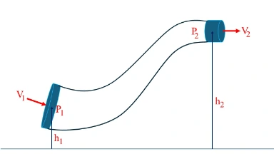
Step-by-step Mechanical Work-Energy Analysis:
-
Work Done by Net Pressure Forces:
Upstream fluid behind the element exerts positive work equal to p1V, while downstream fluid exerts opposing negative work equal to −p2V. The net boundary pressure work is:Wnet = V (p1 − p2) -
Change in Kinetic Energy:
For an element mass m = ρV accelerating from speed v1 to v2:ΔKE = ½ ρV (v22 − v12) -
Change in Gravitational Potential Energy:
As the fluid element changes elevation from vertical height h1 to h2:ΔPE = ρV g (h2 − h1) -
Mechanical Energy Balance Assembly:
Equating net work done to the total change in mechanical energy (Wnet = ΔKE + ΔPE):V (p1 − p2) = ½ ρV (v22 − v12) + ρV g (h2 − h1)Dividing every term by volume V and grouping initial (1) and final (2) states on separate sides yields:p1 + ½ρv12 + ρgh1 = p2 + ½ρv22 + ρgh2 = constant
6.2 Applications of Bernoulli’s Equation
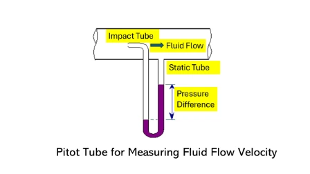
Pitot Tube Flow Meter
A Pitot tube measures the local stagnation pressure p0 created when a fluid stream is brought to rest completely at a probe orifice. Applying Bernoulli’s equation between the undisturbed upstream flow (1) and the stagnation point (0) where v0 = 0:
Venturi Meter Flow Measurement
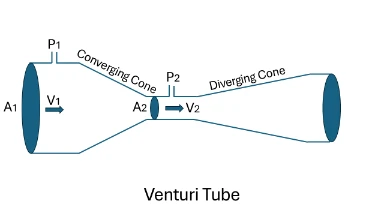
A Venturi meter accelerates fluid by converging cross-sectional area from A1 down to throat area A2, generating a measurable static pressure drop p1 − p2. Combining horizontal Bernoulli energy conservation with mass continuity (A1v1 = A2v2):
Throat Velocity: v2 = √[ 2(p1 − p2) / (ρ (1 − (A2/A1)2)) ]
Volumetric Discharge Rate: Q = A2 v2 = A2 √[ (2(p1 − p2) / ρ) × (A12 / (A12 − A22)) ]
6.3 Assumptions & Limitations
1. Inviscid Flow
Viscous shear stresses are assumed zero. In real boundary layer flows, friction dissipates mechanical energy into heat, requiring inclusion of head loss term hf.
2. Steady State
Local velocity and pressure at any spatial point are time-invariant (∂v/∂t = 0). Unsteady surge or pulsating flows violate this standard balance.
3. Incompressible
Fluid density ρ is strictly constant. Highly accurate for liquids; valid for gas flows only when Mach number M < 0.3.
4. No External Energy
No work input/extraction (pumps or turbines) or thermal energy exchange occurs along the evaluated streamline section.
6.4 Worked Examples
Example 1: Air Velocity Measurement via Pitot Probe
Air (density ρ = 1.2 kg/m3) flows through a duct. A Pitot-static tube indicates a pressure difference p0 − p = 1200 Pa. Calculate the flow velocity.
Solution:
v = √[ 2(1200) / 1.2 ] = √[ 2400 / 1.2 ] = √[ 2000 ] ≈ 44.72 m/s
Example 2: Water Discharge through a Horizontal Venturi Meter
Water (ρ = 1000 kg/m3) flows through a Venturi meter with inlet area A1 = 0.05 m2 and throat area A2 = 0.02 m2. The measured pressure differential is p1 − p2 = 5000 Pa. Determine the volumetric discharge rate Q.
Solution:
A12 / (A12 − A22) = (0.05)2 / [ (0.05)2 − (0.02)2 ] = 0.0025 / [ 0.0025 − 0.0004 ] = 0.0025 / 0.0021 ≈ 1.1905
2 Δp / ρ = (2 × 5000) / 1000 = 10 m2/s2
Q = 0.02 × √[ 10 × 1.1905 ] = 0.02 × √[ 11.905 ] = 0.02 × 3.4503 ≈ 0.058 m3/s (58 L/s)
6.5 Guided Practice Problems
Problem 1: A Pitot tube immersed in a water pipe (ρ = 1000 kg/m3) records dynamic pressure differential Δp = 2500 Pa. Calculate the flow velocity.
View Solution & Answer
Problem 2: Air (ρ = 1.2 kg/m3) flows through a duct from diameter D1 = 0.30 m into a nozzle of diameter D2 = 0.15 m. Given upstream velocity v1 = 5 m/s, determine nozzle exit velocity v2 using continuity.
View Solution & Answer
Problem 3: Water descends vertically through a uniform vertical pipe at constant velocity. Determine the vertical static pressure gradient per meter of downward drop.
View Solution & Answer
6.6 Key Formula Recap
| Formula Name | HTML Equation | Engineering Application |
|---|---|---|
| Bernoulli Equation (Pressure Form) | p + ½ρv2 + ρgh = constant | Mechanical energy conservation along streamlines |
| Bernoulli Head Form | p / (ρg) + v2 / (2g) + h = constant | Hydraulic grade line and total energy head evaluation |
| Pitot Velocity Relation | v = √[ 2(p0 − p) / ρ ] | Flow velocity determination from stagnation pressure difference |
| Venturi Flow Rate | Q = A2 √[ (2 Δp / ρ) × (A12 / (A12 − A22)) ] | Volumetric discharge in converging-diverging flow meters |
| Torricelli Exit Velocity | v = √[ 2gh ] | Free jet discharge velocity from open tank orifice |
6.7 Interactive Venturi & Bernoulli Simulator
Adjust the fluid flow parameters below to observe real-time dynamic pressure drops, velocity acceleration in constricted areas, piezometric head levels, and the static pressure profile across the pipe axis.
6.8 Frequently Asked Questions
Why does static pressure decrease when fluid speed increases through a pipe constriction?
According to mechanical energy conservation, the total mechanical energy along a streamline remains constant. When fluid enters a narrow constriction, mass continuity forces it to accelerate, increasing its dynamic pressure (½ρv2). To keep the energy sum constant, static pressure (p) must drop proportionally.
Can Bernoulli’s equation be applied across different streamlines?
Generally, the Bernoulli constant varies from one streamline to another. However, if the entire flow field is irrotational (zero vorticity, ∇ × V = 0), the constant is identical throughout the fluid, allowing equation application between any two arbitrary points.
How is Bernoulli’s equation modified for real pipe flow with friction?
Real fluids experience viscous friction and boundary layer losses. An additional energy loss term called head loss (hf) is added to the downstream side of the energy head equation: p1/ρg + v12/2g + h1 = p2/ρg + v22/2g + h2 + hf.
What is the upper speed limit for applying Bernoulli’s equation to gases like air?
Bernoulli’s incompressible form remains accurate for gas flows as long as the Mach number remains below approximately M = 0.3 (roughly 100 m/s in ambient air). Beyond this speed, density variations exceed 5% and compressible thermodynamic energy equations must be utilized.
📝 EXERCISES & SELF-ASSESSMENT MODULE
Section 1: Foundational Review Questions
-
What is the fundamental physical statement expressed by Bernoulli’s equation along a streamline?
Answer: Bernoulli’s equation expresses the principle of mechanical energy conservation per unit volume for an ideal, inviscid, steady, and incompressible fluid stream. -
Define the term dynamic pressure and state its mathematical expression.
Answer: Dynamic pressure is defined as ½ρv2. It represents the fluid kinetic energy per unit volume and corresponds to the static pressure rise obtained if the flow is brought to rest. -
What physical quantity does ρgh represent in the Bernoulli relation?
Answer: It represents the hydrostatic potential energy per unit volume of fluid relative to a specified vertical datum level. -
List the four core ideal assumptions required to apply classical Bernoulli equation.
Answer: (1) Steady flow, (2) Incompressible fluid (constant ρ), (3) Inviscid flow (zero viscous friction), and (4) Flow along a single streamline without pump/turbine shaft work. -
Define stagnation pressure and write its equation.
Answer: Stagnation pressure (p0) is the total static pressure measured when fluid is decelerated to zero velocity zero-loss: p0 = p + ½ρv2. -
How does a Pitot-static tube determine local stream velocity?
Answer: By measuring the difference between total stagnation pressure (p0) at the tip and static pressure (p) at side taps, computing v = √[ 2(p0 − p) / ρ ]. -
What is total head in hydraulic energy terms?
Answer: Total head H = p/(ρg) + v2/(2g) + h, representing the total mechanical energy height in meters of fluid column. -
What is the difference between static head and dynamic head?
Answer: Static head is p/(ρg) + h (sum of pressure and elevation heads), whereas dynamic head is v2/(2g) (kinetic energy head).
Section 2: Analytical & Thought-Provoking Scenario Questions
-
Why does an open umbrella tend to turn inside out when blown by strong horizontal wind gusts?
Answer: Air accelerating over the curved top outer surface moves faster than stagnant air trapped underneath. By Bernoulli’s principle, higher upper speed lowers outer static pressure relative to lower surface pressure, producing a strong upward aerodynamic lift force. -
Two high-speed trains pass close to each other on parallel tracks in opposite directions. Why are they drawn toward each other?
Answer: Air squeezed into the narrow gap between the passing trains accelerates rapidly. The increased air velocity drops the static pressure in the central gap below ambient outer pressure, forcing the trains inward. -
In a siphon pipe discharging water over a crest, where is the point of minimum static pressure located?
Answer: Minimum pressure occurs at the highest vertical elevation (crest) of the siphon line, where potential head h is maximum and static pressure drops proportionally. -
Why is Bernoulli’s standard equation invalid across a steep hydraulic jump or acoustic shock wave?
Answer: Hydraulic jumps and shock waves involve severe turbulence, violent energy dissipation, extreme fluid compression, and irreversible mechanical energy conversion into thermal energy, violating inviscid and steady energy conservation. -
A horizontal pipe splits into two branches of different diameters. Assuming no losses, how do the static pressures compare in the branch lines?
Answer: The smaller diameter branch will have higher fluid velocity by continuity, and therefore a lower static pressure than the larger branch. -
Why does cavitation occur in low-pressure throats of Venturi meters if fluid velocity is pushed too high?
Answer: Excessive acceleration drops static throat pressure below the fluid’s vapor pressure at local temperature, causing liquid to flash instantaneously into vapor bubbles that collapse destructively downstream. -
How does the concept of total energy line (TEL) differ from hydraulic grade line (HGL)?
Answer: TEL represents total head p/(ρg) + v2/(2g) + h, while HGL represents piezometric head p/(ρg) + h. The vertical distance between TEL and HGL equals dynamic velocity head v2/(2g). -
How does fluid viscosity inside a pipe boundary layer affect Bernoulli calculations?
Answer: Boundary layer friction converts mechanical flow energy into heat, causing total head to drop continuously along flow direction. Standard Bernoulli overestimates downstream velocity/pressure unless head loss hf is subtracted.
Section 3: Numerical Problems with Detailed Solutions
-
A Pitot-static probe in an airplane flying through standard air (ρ = 1.2 kg/m3) measures a differential stagnation pressure of 800 Pa. Calculate the flight speed.
Solution:Using v = √[ 2(p0 − p) / ρ ]:
v = √[ 2(800) / 1.2 ] = √[ 1600 / 1.2 ] = √[ 1333.33 ] = 36.51 m/s. -
Water (ρ = 1000 kg/m3) flows through a horizontal Venturi meter with area ratio A1/A2 = 4. If throat speed is v2 = 8 m/s, find inlet velocity v1 and expected static pressure drop p1 − p2.
Solution:1. Continuity: v1 = (A2/A1) v2 = (1/4) × 8 = 2.0 m/s.
2. Pressure Drop: p1 − p2 = ½ρ(v22 − v12) = 0.5 × 1000 × (82 − 22) = 500 × (64 − 4) = 500 × 60 = 30,000 Pa (30 kPa). -
A vertical pipe filled with flowing water (ρ = 1000 kg/m3) rises vertically by Δh = 5 m. Assuming constant cross-sectional area and negligible friction, compute the pressure change p2 − p1.
Solution:Since A1 = A2, v1 = v2.
p1 + ρgh1 = p2 + ρgh2 ⇒ p2 − p1 = −ρg(h2 − h1) = −(1000)(9.81)(5) = −49,050 Pa (−49.05 kPa). -
A horizontal Venturi meter measuring water (ρ = 1000 kg/m3) has inlet area A1 = 0.10 m2 and throat area A2 = 0.05 m2. If p1 − p2 = 2000 Pa, find discharge Q.
Solution:Q = A2 √[ (2 Δp / ρ) × (A12 / (A12 − A22)) ]
A12 / (A12 − A22) = 0.01 / (0.01 − 0.0025) = 0.01 / 0.0075 = 1.3333
2 Δp / ρ = 2(2000)/1000 = 4.0
Q = 0.05 × √[ 4.0 × 1.3333 ] = 0.05 × √[ 5.3333 ] = 0.05 × 2.3094 = 0.1155 m3/s. -
An open storage tank holds water to a depth of h = 2 m above a small exit orifice near the bottom. Find the theoretical jet efflux velocity v exiting to atmosphere.
Solution:Applying Torricelli’s relation derived from Bernoulli:
v = √[ 2gh ] = √[ 2 × 9.81 × 2 ] = √[ 39.24 ] = 6.26 m/s. -
Water accelerates through a nozzle from 5 m/s to 15 m/s in a horizontal pipe. What static pressure drop occurs?
Solution:p1 − p2 = ½ ρ (v22 − v12) = 0.5 × 1000 × (152 − 52) = 500 × (225 − 25) = 500 × 200 = 100,000 Pa (100 kPa). -
Air at density 1.20 kg/m3 flows at 20 m/s. Compute its dynamic pressure q in Pascals.
Solution:q = ½ ρv2 = 0.5 × 1.20 × (20)2 = 0.60 × 400 = 240 Pa. -
A diffuser expands horizontally from diameter D1 = 0.05 m to D2 = 0.10 m. If water static pressure increases by p2 − p1 = 1000 Pa across the diffuser, calculate entry velocity v1.
Solution:1. Area ratio: A2/A1 = (D2/D1)2 = (0.10/0.05)2 = 4 ⇒ v2 = v1 / 4.
2. Bernoulli: p1 − p2 = ½ρ(v22 − v12) ⇒ 1000 = ½(1000)(v12 − (v1/4)2)
1000 = 500 × (15/16) v12 ⇒ 2 = (15/16) v12 ⇒ v12 = 32/15 ≈ 2.1333 ⇒ v1 = 1.46 m/s.
Proceed to Next Chapter: Chapter 7: Applications of Fluid Dynamics
Return to Course Index: Prep4Uni Fluid Mechanics 1 Main Page