
🚁 Overview
Overview: Explore common pressure-measurement devices—manometers, Bourdon gauges, spring-loaded manometers, and electronic transducer sensors—and master the hydrostatic equations required to interpret their physical outputs.
📖 Contents
- Manometers
- Bourdon Gauges & Mechanical Variants
- Electronic Sensors
- Mechanical vs. Electronic Transducers
- Key Points Recap
- Comprehensive Practice Exercises
🎯 Learning Outcomes
By the end of Chapter 3: Pressure Measurement, students will be able to:
- Describe the working principles of manometers: Explain how U-tube and differential manometers use hydrostatic balance to measure pressure differences.
- Read and interpret manometer readings: Calculate pressure differences from measured height differences (Δh) using Δp = ρgΔh.
- Explain Bourdon gauge operation: Describe how a curved, flattened tube responds to internal pressure and translates motion into a pointer reading.
- Understand electronic (piezoelectric) sensors: Explain how mechanical stress on a piezoelectric crystal generates an electrical signal proportional to pressure.
- Compare mechanical vs. electronic methods: Discuss advantages, limitations, accuracy, and response time of Bourdon gauges versus piezoelectric and other electronic sensors.
- Summarize key points: Recall major considerations in pressure measurement, including fluid selection, device calibration, and sources of error.
- Select appropriate devices: Choose between manometers, Bourdon gauges, and electronic sensors for given pressure ranges and application requirements.
- Perform unit conversions: Convert between common pressure units (Pa, kPa, bar, psi, mmHg) in the context of device readings.
3.1 Manometers
Manometers measure pressure by balancing unknown fluid pressure against the height difference of a liquid column in a calibrated tube:
-
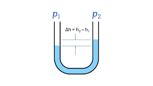
U-tube manometer: A U-shaped tube partially filled with a reference fluid of known density. Pressure difference is expressed as:Δp = ρgΔhwhere Δh is the vertical height difference between the liquid levels in the two arms.
Working Principle of a U-Tube Manometer
Device description
A U-shaped tube is partially filled with a reference manometric fluid of known density ρ. One limb connects to the unknown pressure source P1, and the other limb connects to a second reference pressure source P2 (often ambient atmospheric pressure).
Hydrostatic equilibrium
In a static fluid at equilibrium, pressure is equal at any horizontal plane within the same continuous fluid body. Let the fluid columns stand at heights h1 (under P1) and h2 (under P2) measured from a common horizontal datum line.
Pressure balance equation
Writing a hydrostatic balance from the surface under P1 down to the datum and up to the surface under P2 gives:
Rearranging yields the fundamental differential pressure relation:
where Δh = h2 − h1 is the measured vertical column deflection.
- If P2 = atmospheric pressure Patm, the device reads gauge pressure: Pgauge = P1 − Patm = ρgΔh.
- If both ends see independent enclosed process pressures, the equation yields differential pressure P1 − P2.
Reading the manometer
- Observe both fluid surfaces and measure vertical deflection Δh.
- Calculate differential pressure: ΔP = ρgΔh.
Answer: Convert final calculated value to desired target engineering units (Pa, kPa, bar, psi).
Key considerations
- Density dependence: Denser manometric fluids (e.g., mercury, ρ ≈ 13,600 kg/m3) yield smaller, more compact Δh deflections for high-pressure systems.
- Fluid immiscibility: Multi-fluid differential manometers require immiscible boundaries to avoid fluid mixing and boundary distortion.
- Accuracy: Temperature variations shift fluid density, while capillary surface tension in narrow bore tubes causes meniscus errors. Use wider tubes (> 10 mm diameter) to minimize capillary distortion.
-
Inclined-tube manometer: One limb is tilted at an angle θ to amplify linear deflection along the tube scale, increasing sensitivity for small pressure differences:Δp = ρg(ΔL sin θ)
Example of Pressure Measurement using a U-Tube Manometer
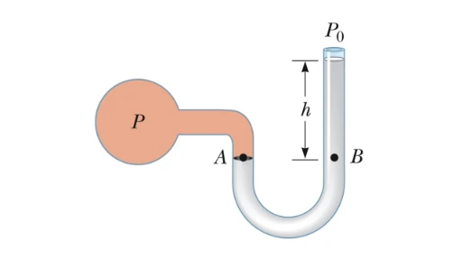
In an open-ended U-tube manometer, one leg is vented to atmosphere (P0) while the other connects to an enclosed gas vessel. At point B, total hydrostatic pressure equals P0 + ρgh. Equating horizontal pressures at points A and B establishes that absolute vessel pressure is P = P0 + ρgh, where gauge pressure equals P − P0 = ρgh.
3.2 Bourdon Gauges & Mechanical Variants
Bourdon tube gauges convert internal fluid pressure directly into mechanical pointer motion across a calibrated dial:
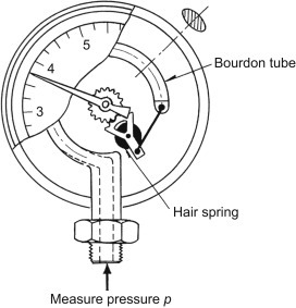
- A flattened, curved C-shaped hollow tube tends to straighten as internal pressure expands its elliptical cross-section.
- The sealed free end connects through a mechanical sector gear and pinion link to drive a center dial pointer.
- Ideal for rugged industrial environments across ranges from 30 kPa up to several hundred MPa.
Spring Manometer Variant
Instead of relying on the Bourdon tube elasticity, mechanical pressure can also be measured by balancing fluid force against a calibrated spring compression.
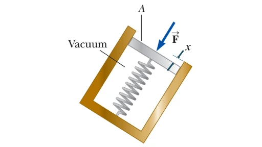
Applied pressure P across piston area A produces force Ffluid = P · A. The spring exerts an opposing force Fspring = k · x, where k is the spring constant and x is linear displacement. At mechanical equilibrium:
3.3 Electronic Sensors
Electronic transducers utilize electrical signal transformation for automated control systems, telemetry, and high-frequency digital logging:
- Piezoelectric sensors: Asymmetric crystalline elements (e.g., Lead Zirconate Titanate, PZT) generate electric charge proportional to applied dynamic mechanical stress. Superior for rapid transient pressure surges.
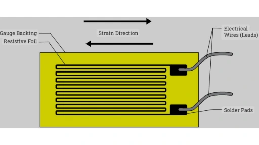
- Strain-gauge sensors: Diaphragm deflection stretches bonded piezoresistive metallic or semiconductor foil grids, changing electrical resistance inside a Wheatstone bridge circuit.
3.4 Mechanical vs. Electronic Transducers
-
Mechanical devices (Manometers, Bourdon gauges):
- Operate passively without external electrical power sources.
- Highly durable, corrosion-resistant, and simple to field-inspect visually.
- Analog display outputs require manual observation.
-
Electronic sensors (Piezoelectric, Strain Gauge Transducers):
- Require regulated power supply excitation.
- High accuracy, fast response time, and minimal hysteresis.
- Provide standard industrial electrical outputs (4–20 mA, 0–10 V) for automated PLC integration.
3.5 Key Points Recap
| Device | Operating Principle | Typical Use |
|---|---|---|
| U-tube manometer | Fluid-column height deflection Δh | Lab standards & low-pressure systems |
| Inclined manometer | Amplified inclined column scale (ΔL sin θ) | High-sensitivity draft/airflow measurements |
| Bourdon gauge | Curved metal tube expansion driving sector gear dial | Industrial pressure monitoring & steam lines |
| Piezoelectric sensor | Crystal surface electric charge under dynamic stress | Combustion, blast waves, & dynamic surges |
| Strain-gauge sensor | Diaphragm resistance shifts in Wheatstone bridge | Automated systems, telemetry, & data loggers |
Interactive U-Tube Manometer Simulator
Adjust applied pressure (P1), manometric fluid density (ρ), and incline angle (θ) to observe fluid column deflection across the timeline scale.
Interactive Pressure Measurement Concept Toggles
Click each section below to toggle in-depth explanations on transducer mechanisms and measurement standards.
Why does tilting a manometer leg in an inclined-tube manometer increase reading sensitivity?
How does zero-drift occur in mechanical Bourdon tube pressure gauges?
Why are piezoelectric pressure sensors suited only for dynamic measurements rather than static pressures?
Frequently Asked Questions
Why is mercury used as a barometric fluid instead of water?
Mercury's high density (≈ 13,600 kg/m3) produces a manageable 760 mm atmospheric column height, whereas water would require a glass tube over 10.3 meters tall.
What is a dead-weight tester used for in fluid calibration labs?
A dead-weight tester acts as a primary calibration standard, generating precise reference pressures by placing known calibrated mass weights onto a piston of precisely machined cross-sectional area (P = mg / A).
How do capillary tube diameter constraints impact manometer selection?
Narrow manometer tubes cause surface tension capillary rise or depression, skewing liquid heights. Selecting sight tube diameters greater than 10 mm minimizes meniscus errors.
📝 Comprehensive Practice Module
Section 1: Foundational Core Assessment
-
What is pressure and what is its SI unit?
Answer: Pressure is normal force applied per unit surface area (p = F / A). Its SI unit is the pascal (Pa), where 1 Pa = 1 N/m2. -
Distinguish between absolute pressure and gauge pressure.
Answer: Absolute pressure (pabs) is measured relative to a absolute zero vacuum baseline. Gauge pressure (pgauge) measures relative to local ambient atmospheric pressure: pgauge = pabs − patm. -
State the hydrostatic pressure equation.
Answer: p = p0 + ρgh, where ρ is fluid density, g is gravitational acceleration, and h is depth. -
How does a U-tube manometer measure a pressure difference?
Answer: By measuring the vertical column height deflection Δh between two fluid limbs and applying Δp = ρgΔh. -
Why is mercury preferred over water in standard barometers?
Answer: Mercury's high density (≈ 13,600 kg/m3) produces a practical atmospheric column height (≈ 760 mm), whereas water requires a column over 10 meters tall. -
Define differential pressure and provide an engineering application example.
Answer: Differential pressure is the static pressure difference between two points (P1 − P2), such as measuring head loss across a pipe filter. -
What is the mechanical operating principle of a Bourdon gauge?
Answer: A flattened, curved metal C-tube uncoils when pressurized internally, translating tip motion into dial pointer rotation through mechanical gearing. -
Convert 2 bar into pascals and pounds per square inch (psi).
Answer: 2 bar = 2 × 10⁵ Pa (200 kPa); 2 bar ≈ 29.01 psi. -
Explain why capillary effects introduce error into narrow-bore manometer tubes.
Answer: Surface tension along narrow tube walls causes capillary rise or depression, shifting the liquid meniscus away from true hydrostatic equilibrium. -
When does a pressure transducer register a negative gauge reading?
Answer: When measured system pressure drops below local atmospheric pressure (vacuum condition).
Section 2: Analytical & Conceptual Analysis
-
Express 1 standard atmosphere (atm) in kPa and mmHg.
Answer: 1 atm = 101.325 kPa ≈ 760 mmHg. -
How does thermal expansion affect pressure readings in closed fixed-volume gas systems?
Answer: By Gay-Lussac's Law (P ∝ T), rising temperature increases gas molecular kinetic energy and pressure, requiring temperature compensation. -
List two key advantages of digital pressure sensors over mechanical Bourdon gauges.
Answer: Higher accuracy/precision and seamless digital output integration with automated SCADA and PLC control networks. -
What is a dead-weight tester and how does it function as a calibration standard?
Answer: It applies known masses onto a piston of precision area, generating a primary reference pressure standard: P = mg / A. -
Why must manometric fluids remain immiscible with the fluid being measured?
Answer: To maintain a distinct, non-reacting liquid interface boundary necessary for accurate column height measurement. -
Define vacuum in terms of gauge and absolute pressure scales.
Answer: Any pressure lower than ambient atmospheric pressure, represented as a negative gauge pressure or an absolute pressure between 0 and patm. -
How does a piezoelectric transducer transform pressure into an electrical signal?
Answer: Applied dynamic stress deforms an asymmetric crystal lattice (e.g., PZT), creating surface electrical charge separation proportional to force. -
Why select a differential pressure sensor over two independent absolute pressure gauges?
Answer: Differential sensors directly measure small pressure drops across system components while canceling out common-mode line pressure fluctuations. -
Why is zero-point adjustment mandatory before operating mechanical pressure gauges?
Answer: To eliminate mechanical zero-shifts, linkage play, or spring pre-loads, ensuring readings start accurately from true ambient baseline.
Section 3: Computational & Numerical Exercises
-
A U-tube water manometer (ρ = 1000 kg/m3) exhibits a column deflection Δh = 0.15 m. Calculate the pressure difference Δp (take g = 9.81 m/s2).
Solution:
Δp = ρgΔh = 1000 × 9.81 × 0.15 = 1471.5 Pa (1.472 kPa). -
Convert a gauge reading of 250 kPa into absolute pressure at sea level (patm = 101.325 kPa).
Solution:
pabs = pgauge + patm = 250 + 101.325 = 351.325 kPa. -
A mercury barometer reads 0.760 m of Hg (ρHg = 13 600 kg/m3, g = 9.81 m/s2). Compute total atmospheric pressure in Pa.
Solution:
p = ρgh = 13 600 × 9.81 × 0.760 = 101 372.16 Pa ≈ 101.37 kPa. -
A pressure gauge reads 50 psi. Convert this reading to kPa (given 1 psi = 6.89476 kPa).
Solution:
50 × 6.89476 = 344.738 kPa ≈ 344.74 kPa. -
In a differential manometer, one limb contains oil (ρ = 850 kg/m3) and the water level is 0.10 m higher on the opposing side. Find Δp.
Solution:
Δp = ρgΔh = 850 × 9.81 × 0.10 = 833.85 Pa. -
A water tank has a depth of 6 m. Calculate the hydrostatic gauge pressure at the bottom (ρ = 1000 kg/m3, g = 9.81 m/s2).
Solution:
p = ρgh = 1000 × 9.81 × 6 = 58 860 Pa (58.86 kPa). -
A dead-weight tester applies a 5 kg mass onto a piston of area 2 cm2. Compute the generated reference pressure in Pa (g = 9.81 m/s2).
Solution:
Area A = 2 × 10⁻⁴ m2.
Force F = 5 × 9.81 = 49.05 N.
p = F / A = 49.05 / (2 × 10⁻⁴) = 245 250 Pa (245.25 kPa). -
A linear pressure transducer outputs 0 V at 0 kPa and 5 V at 500 kPa. Determine the system pressure corresponding to a 3 V output signal.
Solution:
p = (3 V / 5 V) × 500 kPa = 300 kPa. -
A U-tube manometer filled with fluid (ρ = 1200 kg/m3) reads hleft = 0.12 m and hright = 0.18 m. Compute Δp.
Solution:
Δh = 0.18 − 0.12 = 0.06 m.
Δp = 1200 × 9.81 × 0.06 = 706.32 Pa. -
A pressure sensor reads -30 kPa gauge pressure. Calculate the corresponding absolute pressure (patm = 101.325 kPa).
Solution:
pabs = 101.325 + (-30) = 71.325 kPa. -
Convert a standard barometric reading of 760 mmHg into an equivalent head height of water (ρwater = 1000 kg/m3, ρHg = 13 600 kg/m3).
Solution:
p = 0.760 × 13 600 × 9.81 = 101 372.16 Pa.
hwater = 101 372.16 / (1000 × 9.81) ≈ 10.33 m. -
A mercury manometer records a 0.010 m column height difference. Calculate Δp in Pa (ρHg = 13 600 kg/m3).
Solution:
Δp = 13 600 × 9.81 × 0.010 = 1334.16 Pa (1.334 kPa). -
A 0–1 bar pressure transmitter outputs a 4–20 mA current loop signal. What output current represents a measured pressure of 0.5 bar gauge?
Solution:
Span = 20 mA − 4 mA = 16 mA.
Current I = 4 mA + (0.5 bar / 1.0 bar) × 16 mA = 4 + 8 = 12 mA. -
Calculate the capillary height rise in a glass tube of diameter 2 mm filled with pure water (γ = 0.072 N/m, contact angle θ = 0°, ρ = 1000 kg/m3, g = 9.81 m/s2).
Solution:
h = (4 × γ × cos θ) / (ρ × g × D) = (4 × 0.072 × 1) / (1000 × 9.81 × 0.002) ≈ 0.01468 m = 14.68 mm. -
A hydraulic cylinder experiences a gauge pressure of 200 kPa. Calculate the total force exerted on a piston of surface area 0.05 m2.
Solution:
F = p · A = 200 000 Pa × 0.05 m2 = 10 000 N (10 kN).