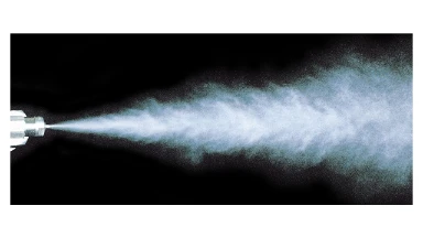
7.1 Flow Through Nozzles and Diffusers
When pipe area changes, so does velocity. In a nozzle (converging section) the flow accelerates and static pressure drops; in a diffuser (diverging section) the flow decelerates and pressure recovers. The behavior follows the continuity equation and Bernoulli’s equation for steady, incompressible, inviscid flow.
- Continuity: \( Q = A\,v \), so \( A_1 v_1 = A_2 v_2 \) (incompressible flow).
- Bernoulli (along a streamline): \( p + \frac{1}{2}\rho v^{2} + \rho g h = \text{constant} \).

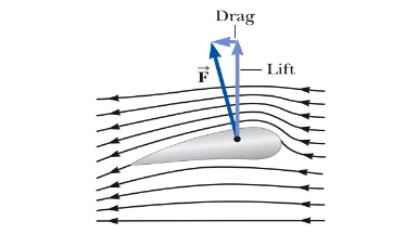
7.2 Lift on Airfoils and the Bernoulli Principle
Faster flow over the cambered upper surface of a wing generally implies lower static pressure than beneath the wing, producing lift. A simple Bernoulli estimate uses the pressure difference between the two sides:
Lift per unit area (pressure difference): \( \Delta p = p_{\text{lower}} – p_{\text{upper}} = \frac{1}{2}\rho\!\left(v_{\text{upper}}^{2} – v_{\text{lower}}^{2}\right) \).
Total lift: \( L \approx \Delta p \, A_{\text{wing}} \). (Real aircraft use circulation/Kutta–Joukowski theory; this is a first‐order estimate.)
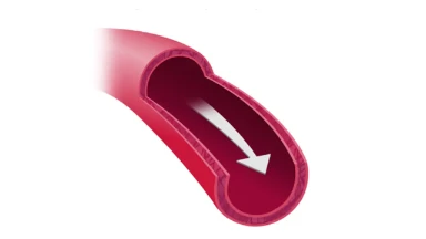
7.3 Blood Flow in Arteries
Blood is well approximated as incompressible. In a narrowed artery (stenosis) the reduced area raises velocity and lowers static pressure, consistent with continuity and Bernoulli.
- Flow rate: \( Q = A\,v \Rightarrow v_2 = v_1 \frac{A_1}{A_2} \).
- Pressure change (horizontal vessel): \( p_2 – p_1 = \frac{1}{2}\rho\!\left(v_1^{2} – v_2^{2}\right) \) (ideal; real blood flow has viscous losses).
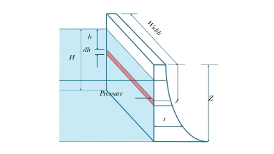
7.4 Loading on Dams
Hydrostatic pressure increases linearly with depth: \( p(h)=\rho g h \). The total horizontal force on a vertical rectangular dam face of width \( b \) and water depth \( h \) is
Total force: \( F=\int_{0}^{h}\rho g y\,b\,dy = \frac{1}{2}\rho g b h^{2} \).
Center of pressure (useful in design): \( y_{\mathrm{cp}}=\frac{\int_0^h y(\rho g y)\,b\,dy}{\int_0^h (\rho g y)\,b\,dy}=\frac{2h}{3} \) below the free surface.
This is for static water. In dynamic conditions (spillways, waves, earthquakes), add kinetic and transient loads; Bernoulli and momentum methods complement structural analysis.
Although \( p=\rho g h \) is linear in \( h \), the bending moment at the base results from the integral of pressure and scales as \( \propto h^{2} \). Designers also include safety factors for waves, uplift, seismic loads, seepage, and material uncertainties, so thickness grows more than linearly.
🤔 Puzzle 2: Why do arch dams curve with the convex side upstream?Water pressure puts the curved upstream face into compression; concrete is strong in compression and weak in tension. The arch action also redirects load into the abutments, reducing material while maintaining safety.
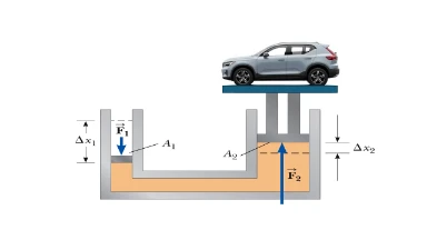
7.5 Hydraulic Lift
By Pascal’s law, a pressure change applied to a confined incompressible fluid is transmitted undiminished: \( p=\frac{F_1}{A_1}=\frac{F_2}{A_2} \Rightarrow F_2=F_1\frac{A_2}{A_1} \).
Volume continuity sets the motion: if the small piston moves a distance \( s_1 \), the large piston rises \( s_2=s_1\frac{A_1}{A_2} \). Thus the lift provides force amplification at the expense of displacement.
7.6 Key Formula Recap
| Concept | Formula |
|---|---|
| Continuity (incompressible) | \( Q=A\,v,\quad A_1 v_1 = A_2 v_2 \) |
| Bernoulli (along a streamline) | \( p + \frac{1}{2}\rho v^{2} + \rho g h = \text{constant} \) |
| Airfoil lift (Bernoulli estimate) | \( L \approx \left(p_{\text{below}}-p_{\text{above}}\right)A = \frac{1}{2}\rho\!\left(v_{\text{upper}}^{2}-v_{\text{lower}}^{2}\right)A \) |
| Hydrostatic pressure | \( p(h)=\rho g h \) |
| Hydrostatic force on dam (width \( b \)) | \( F=\frac{1}{2}\rho g b h^{2} \), center of pressure \( y_{\mathrm{cp}}=\frac{2h}{3} \) |
| Pascal’s law (hydraulic lift) | \( \frac{F_1}{A_1}=\frac{F_2}{A_2} \Rightarrow F_2=F_1\frac{A_2}{A_1} \) |